EasyManua.ls Logo

Turner Designs TD-4100XD E09 - User Manual

Turner Designs TD-4100XD E09
27 pages
Print Icon
To Next Page IconTo Next Page
Loading...
PN 106169
Rev B
E09 TD-4100XD Oil In Water Monitor
Clean-In-Place Addendum
A-1
ADDENDUM: CLEAN-IN-PLACE SYSTEM
This addendum provides the appropriate general arrangement drawings, installation specics, and
operating instructions for an E09 TD-4100XD monitor equipped with an integrated clean-in-place (CIP)
system. The functionality and general operational instructions for your monitor remain as described in
the manual, with the exceptions described in this addendum.
In some cases the arrangement and appearance of your CIP-equipped monitor do not match the
graphic images shown in the manual. If you have questions regarding installation, connections, settings,
procedures, or the general appearance of your monitor, contact a service representative at Turner
Designs Hydrocarbon Instruments:
Tel: + 1 559 253 1414, Fax: + 1 559 253 1090, or
Email: service@oilinwatermonitors.com
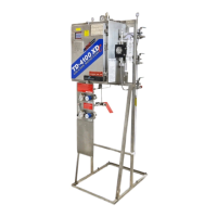
A.1 INSTALLING THE CLEAN-IN-PLACE SYSTEM
The following installation steps include references to Figure A.1.1.
1. Install the valve and pipe combo (1) into
the sample pump discharge port as shown.
Remove the exible hose if required.
2. Install the CIP return port (2) as shown.
Make sure that the union half axis is parallel
to the sample pump discharge port axis.
3. If not yet installed, install the CIP return
port (3) into the 3/4” FNPT tank tting. This
section shall be vertical to the ground. For
best results, install prior to the CIP main
body.

Questions and Answers

Overview

This document describes the Clean-In-Place (CIP) system for the E09 TD-4100XD Oil In Water Monitor, providing installation specifics, operating instructions, and general arrangement drawings. The CIP system automates the cleaning process for the monitor's sample system.

Function Description

The CIP system is designed to automatically clean the sample system of the E09 TD-4100XD monitor. It integrates with the monitor's existing components, including the sample pump, valves, and tank, to ensure proper cleaning and prevent cross-contamination. The system automates the operation of all sample valves, directing fluids to avoid contamination during cleaning. In the event of a power failure, valves will remain in their last state, and upon power restoration, they will revert to the process. During stabilization periods, valves are directed to the outlet. The system can be configured for automatic cleaning on a regular timer, allowing users to set a specific start date, time, and frequency. Manual cleaning is also an option, which stops all processes and measurements, enabling tasks like cleaning the flow cell nozzle with a brush.

Important Technical Specifications

  • Power Supply: The pump and valve actuators are powered by the input mains at 115 VAC. The CIP pump itself is dual voltage (115 VAC or 230 VAC) but must be set to 115 VAC for use with this monitor.
  • Cleaning Solution Pump:
    • Maximum working pressure: 75 psig [517 kPa(g)].
    • Maximum pumping capacity: about 18 U.S. gal/min [68 L/min].
  • Cleaning Solution Tank:
    • Volume: 10 U.S. gal [38 L].
    • Minimum fill level for operation: 5 U.S. gal [19 L].
    • The tank vent, located in the center of the tank cover, must remain open to atmosphere.
  • Piping Connections:
    • CIP pump outlet: 1/2 in. MNPT.
    • Sample return (to process): 1 in. FPT.
    • CIP inlet valve: 1/2 in. CPVC ball valve.
    • Recommended slope for inlet piping: 3° minimum to ensure proper draining.
    • A vacuum breaker (e.g., Plast-O-Matic VBM050V-CP) is strongly recommended near the inlet valve outlet.
    • A pressure regulator is shipped with the monitor and should be installed on the sample water inlet pipe, before the actuator.
  • Electrical Connections:
    • Fuses immediately above terminal blocks: 6.3 A fast acting, except for power (PWR) and CIP pump (I) which use 5 A slow blow fuses.
    • Actuated valves wiring: Black (normally closed), Red (normally open), White (neutral), Green (frame ground).
    • Main power terminal (PWR) wiring: Black (hot), White (neutral), Green (ground).
    • CIP pump terminal block (I) wiring: Black (normally open), White (neutral), Green (ground).
    • CIP tank float switch wiring: Green leads together with a wire nut, white leads together with a wire nut, one black lead to normally open terminal, other black lead to common terminal.
    • Electrical connections must conform to IEC 60079-14.
  • Environmental: The pump can be damaged by fluid below 35 °F [4.4 °C].

Usage Features

  • Installation: The addendum provides detailed, step-by-step instructions for installing the CIP system, including connecting the valve and pipe combo to the sample pump discharge, installing the CIP return port, and installing the float valve switch. It emphasizes proper tightening of joints and fasteners.
  • Configuration: The cleaning system operation is configured through the E09 monitor's keypad. Users can access cleaning settings from the Home screen, enter a user access code (8520), and then set the cleaning timer, start date, time, and frequency.
  • Cleaning Sequence: The cleaning cycle involves a series of timed steps, including:
    1. Inlet OFF (closing the inlet valve and draining the inlet tubing).
    2. Drain Open (opening the bubble trap valve).
    3. Drain Close (closing the bubble trap valve).
    4. Outlet OFF (closing the outlet valve).
    5. Clean Pump ON (pumping cleaning solution through the system).
    6. CIP Pump OFF (shutting off the pump and draining cleaning solution back to the tank).
    7. Drain Valve - Open (opening the bubble trap valve to drain back to the tank).
    8. Drain Valve - Close (closing the bubble trap valve).
    9. Outlet - ON (returning the outlet valve to process).
    10. Inlet - ON (returning the inlet valve to process).
  • Recommended Durations: The manual provides recommended duration settings for each step of the cleaning cycle, determined from a test configuration with specific piping lengths and slope.
  • Manual Operation: The system can be manually started or stopped. Pressing "2" on the Cleaning screen allows for manual cleaning, stopping all processes and measurements.
  • Safety Notes:
    • Always secure the cover on the cleaning solution tank before operating the CIP system.
    • Ensure the cleaning solution tank is at least half full (5 U.S. gal) before operating.
    • The cleaning solution must be compatible with the process downstream of the monitor, as a portion may be directed into the monitor's drain line.
    • The Clean Pump ON time must be at least 90 seconds to allow the bubble trap to fill and the pressure sensor to trigger the AVS.
  • Monitor Behavior During Cleaning:
    • Oil concentration measurements stop.
    • The 4-20 mA output remains proportional to the last measured oil concentration.
    • All monitored alarms remain in their last state set during normal operation.

Maintenance Features

  • Pre-Use Checks: Before each use, verify that at least 5 U.S. gal [19 L] of cleaning solution is present in the tank.
  • Cleaning Solution Management: Periodically drain and replace the cleaning solution. The type of cleaning solution should be chosen based on the fouling type and compatibility with CIP system and monitor materials (316 stainless steel and CPVC).
  • Leak Prevention: Ensure all threaded and tubing connections are tight and leak-free.
  • Pump Maintenance:
    • For extended shutdown, flush the pump to prevent fluid from drying or freezing.
    • The pump will require periodic overhaul, though the exact interval is not defined.
    • Before any maintenance or overhaul, shut off the sample supply, allow the pump to operate until empty, flush if necessary, turn off power, and uncouple the power line. Remove the pump from its mounting for repair work.
    • Turner Designs Hydrocarbon Instruments recommends establishing a preventive maintenance schedule based on the pump's service history to prevent spills or leakage due to pump head failure.
  • Automated Valves/Actuators: No expected maintenance is required for the automated valves or actuators.
  • Troubleshooting: The manual includes a troubleshooting section that lists common problems, their causes, and solutions. These include:
    • Insufficient cleaning: Caused by short cleaning cycle duration or ineffective cleaning solution. Solution: Increase duration or use a different solution.
    • Automated valves failing to switch: Caused by incorrect wiring. Solution: Check wiring connections.
    • Pump not running or running slowly: Caused by incorrect voltage, blockage, no fluid in tank, or blown fuse. Solution: Check wiring, disassemble pump, check fill level, replace fuse.
    • Pump runs but little or no liquid flows: Caused by loose fluid connections. Solution: Tighten connections.
    • Pump rattles or excessively vibrates: Various issues. Solution: Contact Turner Designs Hydrocarbon Instruments.
  • Important Troubleshooting Note: Always check all possible problems and causes before disassembling the pump.

Turner Designs TD-4100XD E09 Specifications

General IconGeneral
BrandTurner Designs
ModelTD-4100XD E09
CategoryMeasuring Instruments
LanguageEnglish

Related product manuals