Do you have a question about the Tuthill GlobalGear GG250 and is the answer not in the manual?
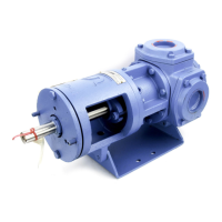
Overview of the maintenance training module for GlobalGear pumps with cartridge mechanical seals.
Steps for installing the rotor, bearings, and bearing carrier into the pump bracket.
Procedure for positioning the mechanical seal, aligning flush ports, and installing the locknut.
Table detailing torque specifications for various locknut and pump sizes.
Ensuring correct gasket position and alignment of flush ports for proper flow.
Positioning the drive module over the foot and housing, then securing with bolts.
Loosen set screws, tighten hex nuts until rotor touches cover, checking for slight drag.
Measure gap at four points, adjust set screws/nuts for uniformity, record zero clearance.
Calculate target gap, perform final tightening, and confirm free shaft rotation.
Measure clearance between rotor and housing, then adjust using hex nuts and set screws.
Table of recommended torque values for M6, M8, M10, and M12 fasteners.
Seal tightening is the last step; gland nuts are started loosely to preserve travel range.
Tighten gland nuts and seal set screws in an even alternating pattern.
Procedure to remove fasteners securing the relief valve and then remove the valve and its gasket.
Diagram of relief valve parts: Cap, Bonnet, Spring Guide, Spring, Poppet, etc.
Steps to remove the cap, jam nut, bonnet, spring guide, spring, and poppet.
Differentiating between high pressure (orange paint) and standard pressure (no bands) springs.
Poppet/seat cleanliness affects bypassing; low set pressure causes chattering or bypassing.
Clean poppet/seat; increase relief valve setting or use a higher pressure spring.
Measure current bypass pressure, calculate target (50% higher), and adjust using nuts.
Tighten jam nut, replace cap, open valve. Complete in 10 mins; avoid overheating.
Reassemble by installing poppet, spring, and spring guide in inverted valve.
Reinstall the bonnet and cap using pipe dope on threads.
Remove bearing cover fasteners, cover, outer cap hex nuts, and outer bearing cap.
Remove inner bearing cap fasteners, push cap back, use bearing puller for shrunk-fit bearings; do not reuse.
Use recommended lubricant and grease gun; add grease until old grease shows color change.
Press out with hydraulic press; install with one forceful movement to avoid breakage.
Press out with hydraulic press, heat bracket/idler to 425°C, follow safety for hot materials.
Ensure cleanliness of fittings, guns, and environment; use recommended lubricants.
Proactive maintenance is cost-effective; temp/vibration increases signal need.
Record monthly bearing temperatures and vibration levels for pump, gear reducer, and motor.
| Brand | Tuthill |
|---|---|
| Model | GlobalGear GG250 |
| Category | Water Pump |
| Language | English |