CONNECTEURS 31 VOIES MT/SPT
31-WAY MT/SPT CONNECTORS
7 de 12Rév. D
411-15599
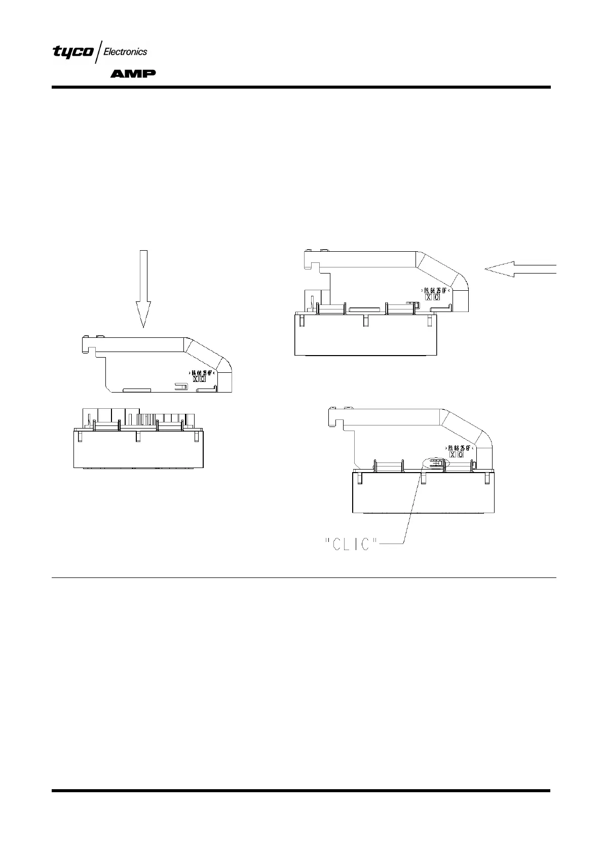
4.1.3. Mise en place du faisceau et capot horizontal
→ Former le toron de câble vers la droite ou la gauche
selon la sortie choisie.
→ Mettre en place le capot (livré à part) comme indi-
qué dans les schémas ci-dessous :
→ Une fois le capot verrouillé, installer le toron dans
la goulotte du capot et positionner un collier serre-
câbles de largeur comprise entre 3,6 et 4,8 mm
dans la gorge de la goulotte.
L’attache du serre-câble doit se trouver sur l’un des
côtés de la goulotte (voir dessin) pour obtenir un
serrage optimal avec un encombrement minimum
(efort de serrage maxi : 220 N).
Figure 4
puis glisser celui-ci vers la droite ou la gauche
selon la sortie choisie.
Un "clic" indique le verrouillage du capot sur le boîtier.
Placer le capot dans les rampes du boîtier
puis glisser celui-ci vers la droite ou la gauche
selon la sortie choisie.
Position the cover in the guides on the housing
A "click" sound indicates that the cover is latched on the housing.
Un "clic" indique le verrouillage du capot sur le boîtier.
4.1.3. Fitting the loop and horizontal cover
→
Route the cable strand to the right or left, depending
on the selected outlet.
→
Fit the cover (supplied separately) as shown in the
diagrams below:
→
When the cover has been latched, fit the cable
strand in the channel in the cover and position a
cable clamp between 3.6 and 4.8 mm wide in the
recess on the channel.
The cable clamp fastener must be located to one
side of the channel (see drawing) in order to obtain
optimal clamping with minimum size (max. clam-
ping force: 220 N).
Then slide the housing to the right of left,
depending on the selected outlet.
Puis glisser celui-ci vers la droite ou la gauche
selon la sortie choisie.