801AP
17A-05-AP
2 11/02
© 2002 Tyco Safety Products PAGE 5 of 10
Registered Office: First Floor North Building Walden CourtParsonage Lane Bishopís Stortford Herts CM23 5DB
EQUIPMENT:
PUBLICATION:
ISSUE No. & DATE:
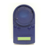
In Fig. 8 pressing F1 selects the ‘Menu’, F2-F4 are redundant
here.
3.5 FUNCTIONALITY
ADDRESS PROGRAM
(See also ‘STORE SETTINGS’ to clear the used address
memory).
The main menu starts with ADDRESS PROGRAM. Press
buttons F2 or F3 to choose ‘Select’ and the address of the
device is displayed
(eg, address 4 ).
• Use ‘Write’ to program the device with a new
address
• ‘Menu’ to return to the main menu
Note: Whenever ‘Menu’ appears on the display, this
always returns to the main menu.
If ‘Write’ is selected, the following screen is displayed:
• Use ‘Up’ to increase the address number
• ‘Dn’ to decrease it
• ‘Write’ to program the address displayed
• ‘Back’ to return to the previous screen
Fig. 8 Example of Single Option
If ‘Write’ is selected then the following message will appear
for 2 seconds:
This is followed by:
Having programmed an address, the Service Tool moves to
the next sequential address. This may be used or available.
If an address has already been used, the Service Tool
indicates:
The user has the choice to continue with a used address, or to
move to the next sequential address, using the up and down
(Dn) buttons.
If the user decides to use a previously used address, the
following screen is displayed:
Press ‘Write’ and the Service Tool displays
‘PROGRAMMED OK’ briefly and then displays the next
sequential address.
The Service Tool uses a memory map of the addresses that
have been programmed. To erase this, select ‘Store Settings’
from the main menu and choose Clear Used ‘ClU’.
ANALOGUE VALUES
ANALOGUE VALUES displays the analogue values of the
attached device.
The above example shows a device with 2 channels, eg, an
Optical/Heat detector, where channel 1 is the optical value
and channel 2 is the heat value. Press ‘Menu’ to return to the
main menu.
CHANNEL 1 CHANNEL 2
SEE NOTE 1