I.S. SYSTEM 800
17A-13-I
11/03
© 2003 Tyco Safety Products PAGE 5 of 14
EQUIPMENT:
PUBLICATION:
ISSUE No. & DATE:
3.2.2 EQUIPMENT PERMITTED IN
HAZARDOUS AREA
The equipment permitted in the Hazardous Area is detailed in
Table 4.
4. CHECKING THE EQUIPMENT
WARNING:
ALL INSTALLATION PRACTICES EMPLOYED
MUST, IN ADDITION TO THE FOLLOWING
INSTRUCTIONS MEET THE REQUIREMENTS
SPECIFIED IN THE CURRENT EDITION OF BS EN
60079-14. ALL ELECTRICAL EQUIPMENT,
INCLUDING MEASURING INSTRUMENTS, USED
IN THE HAZARDOUS AREA MUST FIRST BE
ACCEPTABLE TO THE CUSTOMER’S SAFETY
OFFICER.
a) The system documentation should be read and
understood before proceeding with any
installation work.
b) Ensure that the correct number and type of
enclosures, isolating I.S. interface and sounder
interface units have been supplied.
c) Ensure that all devices for use in the hazardous
area(s) are as specified and have been certified
for the type of risk concerned.
d) Ensure that the cable used between each
isolating I.S. interface and the device(s) in the
hazardous area meets the certification
requirements for the type of risk
concerned. The cable between each isolating
I.S. interface and control equipment zone
terminals must comply with the requirements
laid down in Publication 17A-13-D.
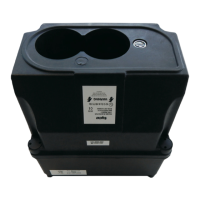
Apparatus Approval No. Permitted Temp. Class
I.S. 28 BANSHEE Ex86B2344 FOUR T6
Table. 4 Equipment to be installed in the Hazardous
Area
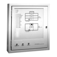
5. MOUNTING THE EQUIPMENT
5.1 I.S. INTERFACE
a) Remove the enclosure front cover.
b) Remove the internal fixings.
c) Choose a method of mounting suitable for the
type of wall.
d) Fix the mounting lugs (if specified).
e) Knock out any conduit/cable gland holes and/
or remove the gland plates and drill the
required holes (the method of entry to the
apparatus should be such as to minimize the
risk of mechanical damage to cables: BS EN
60079-14).
f) Using the internal fixing holes or fixing lugs as
a template, fix the enclosure to the wall (see
Figs. 1 to 2). Suitable clearance should be
allowed for removing the front cover.
g) Replace the internal fixings and front cover.
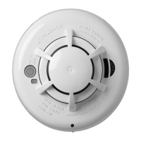
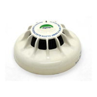
5.2 DETECTORS AND CALLPOINTS
Site the detector bases, addressable interface modules and
callpoints in the positions shown on the Installation Diagram
(refer to System Documentation).
5.3 SOUNDERS
Site the sounders in the positions shown in the Installation
Diagram.
5.4 SYSTEM CONDUITS AND CABLES
Refer to 17A-13-D for cable parameters and to ascertain the
cable requirements for a system. Install the cables as follows:
a) Run the conduits/cables between the devices
in the hazardous area and the I.S. Interface
ensuring that they enter the enclosure via the
holes designated ‘I.S. Wiring only’.
b) Run the conduits/cables between the control
equipment and the I.S. Interface ensuring
that they enter the housing via the holes
designated ‘Non-I.S. Wiring’. (The method
of entry to apparatus should be such as to
minimize the risk of mechanical damage to
cables: BS EN 60079-14).
c) Ensure physical separation of at least 50mm
is maintained between the I.S. and Non-I.S.
wiring throughout, including inside the I.S.
Interface.
www.acornfiresecurity.com
www.acornfiresecurity.com
 Loading...