Wiring diagram
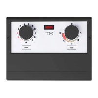
Installation instructions for h1
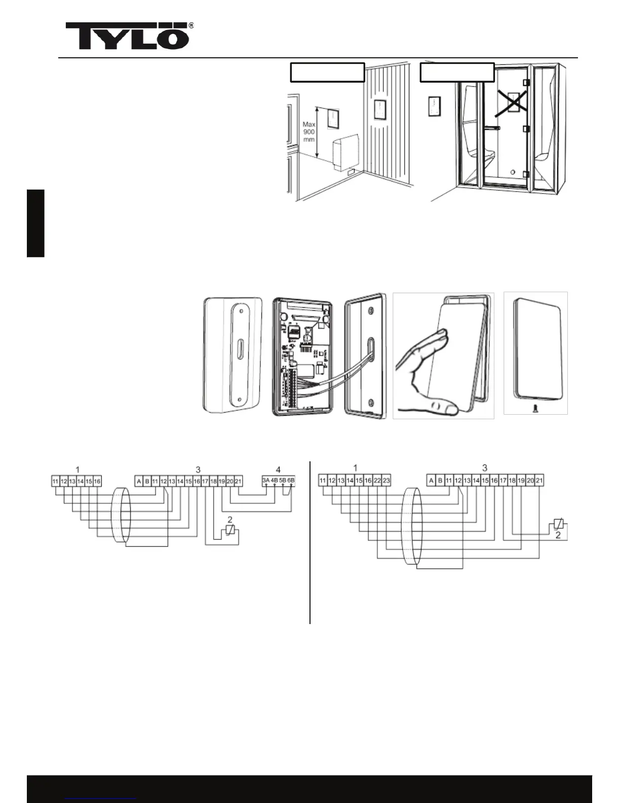
The h1 can be placed inside or outside the
sauna room and outside the steam room. If
the h1 is placed inside a sauna room, the
top edge must not be more than 90 cm
above the floor (figure 1).
Begin by fitting the rubber seal if this is
necessary (figure 2).
It is possible to connect an optional external switch to the h1 panel via terminals 19 and 20 on the
circuit board (also via 21 if you wish to have an indicator signal). See Wiring diagram (figure 6).
Momentary connection: switches on and off respectively each time it is pressed.
Constant connection: the panel is activated for as long as the connection is maintained, up to the
maximum running time that has been set.
When the heater is on, the indicator lamp on the external switch lights up. If the panel has been
programmed to start at a later time, the indicator lamp flashes.
An external switch can not be used with Combi Compact.
12
Figure 6
1.Combi Compact RC
2.Thermistor (sensor)
3.h1
Figure 7
English
1.Sauna heater/steam generator
2.Thermistor (sensor)
3.h1
4.External switch
Figure 2
Figure 3
Figure 4 Figure 5
Steam roomSauna room
Figure 1
This seal should be fitted if the h1 is to be used in a steam room or a humid environment. Screw
the mounting plate into place at a suitable location, making sure that the electric cables pass
through the opening. Note that the plate must be oriented so that the hole for the retainer screw
is on the underside. Screw the electrical connections into place on the terminal block as shown
in the wiring diagram (figures 3, 6 and 7). To facilitate this process, the terminal block can
be removed from the circuit
board. Slide the glass and
circuit board of the control
panel upwards into place on
the mounting plate and
press the bottom edge into
place (figure 4). Screw the
retainer screw into place
(figure 5).