LEA-5, NEO-5, TIM-5H - Hardware Integration Manual
GPS.G5-MS5-09027-A2 Released Design-in
Page 49 of 68
1525 1550 1625
GPS input filter
characteristics
1575 1600
0
-110
Jammin
g signal
1525 1550 1625
Frequency [MHz]
Power [dBm]
GPS input filter
characteristics
1575 1600
0
Jamming
signal
GPS
signals
GPS Carrier
1575.4 MHz
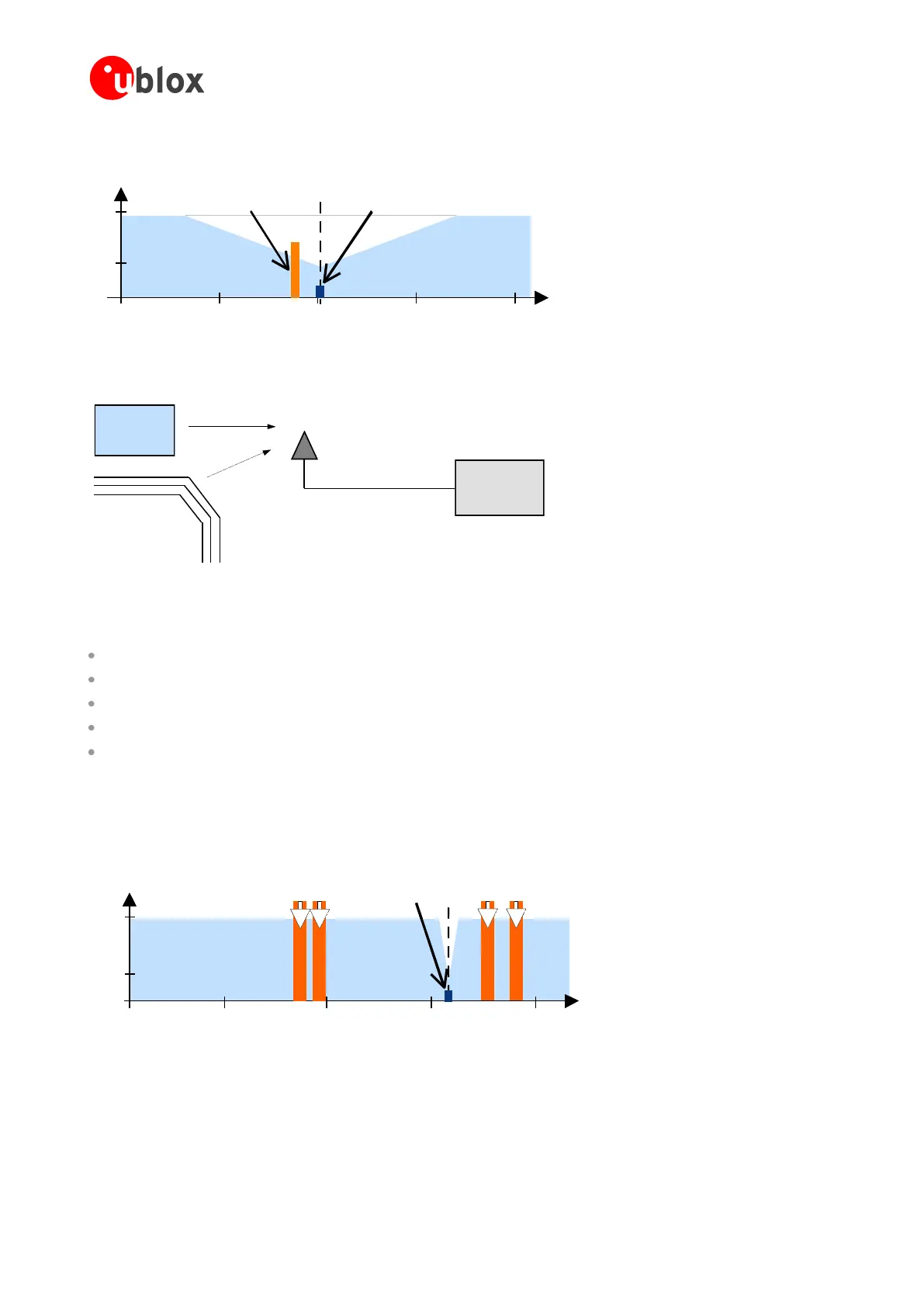
Figure 41: In-band jamming signals
u-blox
5 LNA
u-
blox GPS
receiver
CPU
data bus
Figure 42: In-band jamming sources
Measures against in-band jamming include:
Maintaining a good grounding concept in the design
Shielding
Layout op emperature iltering
Placement of the GPS antenna
Adding a CDMA, GSM, WCDMA bandbass filter before handset antenna
2.7.7.4 Out-band jamming
Out-band jamming is caused by signal frequencies that are different from the GPS carrier (see Figure 43). The main
sources are wireless communication systems such as GSM, CDMA, WCDMA, WiFi, BT, etc..
0 500 1000 1500 2000
GPS input filter
characteristics
0
-110
0 500 1500 2000
Frequency [MHz]
GSM
900
GSM
1800
GSM
1900
Power [dBm]
GPS input filter
characteristics
GPS
1575
0
-110
GPS
signals
GSM
950
Figure 43: Out-band jamming signals
Measures against out-band jamming include maintaining a good grounding concept in the design and adding a
SAW or bandpass ceramic filter (as recommend in Section 2.7.5) into the antenna input line to the GPS receiver
(see Figure 44).

 Loading...
