This document serves as an installation guide for U-Line Icemaker Series products, providing comprehensive instructions for setup, operation, and maintenance. It is designed to assist users in properly installing and caring for their U-Line ice maker units, ensuring optimal performance and longevity.
The guide begins with crucial safety precautions, emphasizing the importance of reading all instructions before installation, operation, or servicing. It highlights the necessity of proper installation procedures, especially when relocating a unit, and advises consulting the guide before any installation begins. A dedicated 15 Amp grounded (three-prong), polarized receptacle, installed by a qualified electrician, compliant with applicable electrical codes, is required for the unit's connection. Safety alert definitions are provided, categorizing risks as Danger, Warning, or Caution based on their severity. General precautions include using the appliance for its intended purpose only and following specific guidelines to prevent child entrapment, electrical shock, and personal injury. Users are warned against attempting repairs or maintenance without disconnecting power, removing the grounding prong, or using extension cords. The importance of keeping the working area dry and installing the provided Anti-Tip kit on relevant models is stressed. Cautionary notes advise care when moving and handling the unit, using gloves to prevent injury from sharp edges, and avoiding sharp instruments or heaters for defrosting to prevent damage to the unit's lining or cooling system. Important operational guidelines include not lifting the unit by the door handle, avoiding installation behind closed doors, ensuring the front grille is free of obstruction for proper airflow, and cleaning the condenser every six months to prevent malfunction. Users are also advised to allow the unit temperature to stabilize for 24 hours before use and not to block any internal fans. The use of genuine U-Line replacement parts is recommended to maintain warranty validity and unit performance.
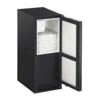
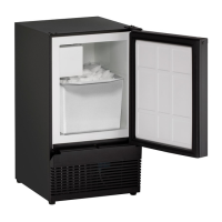
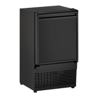
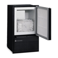
The "Inspect & Plan" section covers product registration, models covered by the guide, and tools/materials required for installation. Users are instructed to complete and mail the Product Registration Card or register online. The guide specifies that it covers various U-Line icemaker models, including ADA15IM, BI-95(B)(WH), BI-98, BI-2115, SP-18, SS-1095NF, SS-1095FC, SS1095FD, BCM95, WH95TP, and B95BTP. Required tools include screwdrivers, nut drivers, side cutters, a copper tubing cutter, a 12" level, open-end wrenches, and pliers. A complete water hook-up kit is also available for purchase. Exterior cleaning instructions are provided for both black/white and stainless steel models. Black and white surfaces can be cleaned with a mild detergent and warm water solution, avoiding solvent-based or abrasive cleaners. Stainless steel surfaces require monthly cleaning with a quality all-in-one stainless steel cleaner/polish to prevent discoloration and rust, especially when exposed to chlorine gas, pool chemicals, or salt water. Users are warned against using steel wool, abrasive pads, or cleaners not specifically intended for stainless steel. Any discoloration or rust should be cleaned quickly with non-abrasive cleansers and the process finished with a stainless steel polish.
The "Prepare Site" section details cut-out dimensions for various models, emphasizing that U-Line products are designed for either free-standing or built-in installation. When built-in, no additional air space is required for the top, sides, or rear, but the front grille must not be obstructed, and clearance is needed for electrical and water connections in the rear. A crucial note states that units cannot be installed behind a closed cabinet door. Detailed diagrams illustrate the minimum cut-out dimensions for each model, including height, width, and depth, along with locations for electrical and water supply connections.
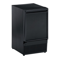
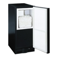
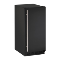
"Product Dimensions" provides detailed diagrams and measurements for each icemaker model, including ADA15IM, BI-95(B)(WH), BI-2115, B195BTP, B198 & SS98, SS1095FD, SP18, SS1095FC, BCM95, SS1095NF, and WH95TP. These diagrams show the overall dimensions of the units, including depth with clearance for water lines, to aid in proper planning and installation.
"Door Swing Dimensions" explains that all units have a zero clearance for the door to open 90 degrees, but a minimum door clearance of 2 inches is recommended to accommodate the handle if the unit is installed next to a wall. Diagrams illustrate door swing dimensions for models like ADA15IM, BI98, SP18, SS1095NF, SS1095FC/FD, WH95, BI95BTP, and BCM95, showing minimum clearances from walls for both with and without handle configurations.
"Other Site Requirements" covers power supply, water supply, and environmental requirements. All units require a grounded and polarized 115 VAC, 60 Hz, 15A circuit. Water supply units need a 1/4" OD water supply line and a shut-off valve. Environmental requirements specify an operating range of 50°F (10°C) to 100°F (37°C). High ambient temperatures may reduce cooling ability and ice production. If ambient temperature drops below 45°F (7°C), all water must be drained to prevent freezing damage. For best performance, units should be kept out of direct sunlight and away from heat-generating equipment. Outdoor units should be placed under a counter or provided shelter. Condensation on outside surfaces in high humidity is considered normal.
"Door Reversal" provides step-by-step instructions for reversing the door swing for various models (B195 & B198; WH95TP, B195BTP, BCM95 & SP18; SS1095). This feature allows units to be configured for left- or right-hand opening based on user preference or installation requirements. Instructions include removing hinges, relocating plastic plugs and spacers, inverting pivot screws, and reinstalling components on the opposite side. Specific details are provided for each model group, ensuring accurate door reversal.
"Door Panel Installation" guides users through preparing and installing custom door panels. For models like BI-95, BI-2115B(WH), and WH95BTP, custom panels can be flat or raised, with a maximum thickness of 1/4 inch. Raised panels may reduce the door's 90-degree swing. Instructions include removing the door handle, sliding the custom panel into the door's channel, and reattaching the handle and gasket. For models 98, SP18, & ADA15, users are cautioned about sharp insert edges. The process involves removing the top hinge screw pin, tilting the door, pulling out the door gasket, and then installing the insert.
"Adjust Door" explains how to check and adjust door alignment to ensure a proper seal. The door gasket should be firmly in contact with the cabinet all the way around. Instructions for BI-2115 models involve loosening bottom hinge plate screws and moving the hinge plate to adjust the door's vertical alignment. For all other models, users are instructed to loosen top and bottom hinge screws, align the door squarely with the cabinet, and then tighten the screws.
"Power Supply" reiterates electrical specifications, emphasizing the need for a grounded and polarized 115 VAC, 60 Hz, 15A circuit. It warns against removing the grounding prong, using two-prong adapters, or extension cords. GFCI is generally not required for fixed location appliances but local codes should be consulted. Diagrams show preferred and acceptable receptacle locations for different models.
"Plumbing" provides guidelines for water supply connection, stressing that all plumbing installations must comply with state and local codes and be performed by a licensed/qualified plumbing contractor. The water supply should be connected to cold water, with pressure between 20 and 120 psi, and include a 1/4" O.D. supply line with a shut-off valve. Approximately 8 feet of copper water line should be coiled behind the appliance for servicing. Users are warned against using plastic water supply lines due to pressure and potential for cracking or rupture. Instructions detail connecting the copper line to the main water source and then to the solenoid valve, avoiding kinks. For front-mounted water solenoids, the grille must be removed.
"Install" covers leveling information, installation steps, and grille installation. For ADA15IM & BI-2115 models, the unit should be level from front to back and side to side, with adjustable feet for leveling. The unit's top surface should be approximately 1/8" below the countertop. For other models, it is crucial that the units sit on a level surface as they do not have feet levelers, and an unlevel surface can affect ice mold filling. Installation involves opening the water supply valve, plugging in the power cord, gently pushing the unit into position, and re-checking leveling. Grille installation instructions vary by model, generally involving aligning hook-hinges or tabs and securing the grille with screws.
"Installation Troubleshooting" offers solutions for common issues. If water is leaking under the unit, the problem is likely a bad connection in the water supply line, requiring tightening of the brass fitting and ensuring no plumbers tape was used. For BI-2115 specific issues, if the door remains open, hinges should be checked for cleanliness, grease, and correct installation, and leveling re-checked. If a custom overlay door has crept forward, ensuring the electrical cord and water supply line are not obstructing the installation is advised.
The guide concludes with "Service Information," providing contact details for general inquiries, service assistance, and parts assistance for U-Line Corporation. It also includes an "About U-Line" section, highlighting the company's history as a leader in built-in undercounter ice making, refrigeration, and wine storage appliances since 1962, emphasizing its commitment to innovation and quality.