66
Crankcase ventilation system
The system maintenance includes a periodic check of the
hermetic-tightness of joints and cleaning gum residue off of the
system components.
In case of increased oil consumption for burn-out loss and
occurrence of black smoke out of the exhaust pipe, check the
crankcase ventilation system for proper condition (clogging of
channels).
The crankcase ventilation system proper condition is checked
using the water piezometer connected to the crankcase via the
oil level indicator tube.
In the crankcase of an idle running engine (with crankshaft
rpm minimum to maximum), there shall be negative pressure
of 1-14 mbar (10-140 mm WG).
If oil traces appear on the joint between the turbocharger
and the inlet pipe, check the crankcase blow-by gases pressure.
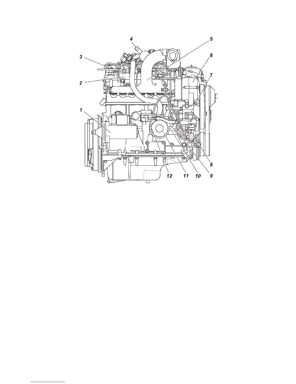
Fig. 9.12. ZMZ-51432 engine (right-side view):
1 — starter; 2 — fuel rail; 3 — phase sensor; 4 — pipe of cooling fluid removal
to the heater; 5 — inlet pipe; 6 — generator; 7 — high-pressure fuel pump
(HPFP); 8 — timing sensor; 9 — pressure sensor; 10 — liquid-oil heat exchanger;
11 — oil filter; 12 — oil pump drive cover
 Loading...