5 GHz, 19 dBi
airMAX
®
ac CPE
Model: NBE-5AC-19
Introduction
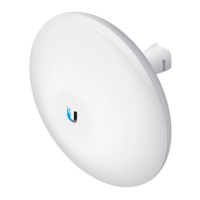
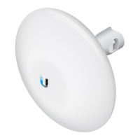
Thank you for purchasing the Ubiquiti Networks®
NanoBeam®ac. This Quick Start Guide is designed to guide
you through installation and also includes warranty terms.
Package Contents
NanoBeam ac Ball Joint
Mount
Lock Ring
5 GHz, 19 dBi
airMAX
®
ac CPE
Model: NBE-5AC-19
Metal Strap Gigabit PoE (24V, 0.5A)
with Mounting Bracket
Power Cord Quick Start
Guide
TERMS OF USE: Ubiquiti radio devices must be professionally installed. Shielded Ethernet
cable and earth grounding must be used as conditions of product warranty. TOUGHCable
™
is
designed for outdoor installations. It is the customer’s responsibility to follow local country
regulations, including operation within legal frequency channels, output power, and Dynamic
Frequency Selection (DFS) requirements.
Installation Requirements
The NanoBeam can be mounted on a pole or to a wall. A Metal
Strap (included) is used for pole-mounting. For wall-mounting,
a suitable fastener such as a screw or bolt (not included) is
required.
• Pole-mounting: 7 mm socket wrench or screwdriver
• Wall-mounting: wall fastener (not included)
• Shielded Category 5 (or above) cabling should be used for
all wired Ethernet connections and should be grounded
through the AC ground of the PoE.
We recommend that you protect your networks from the
most brutal environments and devastating ESD attacks with
industrial-grade shielded Ethernet cable, TOUGHCable from
Ubiquiti Networks.
For more details, visit www.ubnt.com/toughcable
Hardware Overview
LEDs
Reset Button Ethernet Port
(10/100/1000 Mbps)
Reset Button To reset to factory defaults, press and hold the
Reset button for more than 10 seconds while the NanoBeam
is already poweredon. Alternatively, the NanoBeam may be
reset remotely via a Reset button located on the bottom of the
Gigabit PoE Adapter.
Ethernet Port This Gigabit Ethernet port is used to connect
the power and should be connected to the LAN and DHCP
server. Power can be provided by any of the following:
• Gigabit PoE Adapter (included)
• Ubiquiti Networks TOUGHSwitch
™
PoE
• Ubiquiti Networks EdgeSwitch
™
or EdgeRouter
™
PoE
LEDs
Power The Power LED will light blue when the
device is connected to a power source.
Ethernet The Ethernet LED will light steady blue
when an active Ethernet connection is made and
flash when there is activity.
Signal The default values are shown below:
LED will light blue when the wireless signal
strength is equal to or above -94 dBm.
LED will light blue when the wireless signal
strength is equal to or above -80 dBm.
LED will light blue when the wireless signal
strength is equal to or above -73 dBm.
LED will light blue when the wireless signal
strength is equal to or above -65 dBm.
Hardware Installation
The NanoBeam can be mounted on a pole or to a wall. Perform
the steps for the appropriate installation:
Pole-Mount
1. Insert the Ball Joint Mount into the Lock Ring with the
threads of the Lock Ring facing the ball joint.
2. Open the Metal Strap and feed it through the base of the
Ball Joint Mount.
*640-00127-08*
640-00127-08
3. Wrap the Metal Strap around the pole. Use a 7 mm socket
wrench to turn the screw clockwise and securely fasten the
clamp to the pole.
4. Attach the NanoBeam to the Ball Joint Mount and turn the
Lock Ring to secure it. Keep the Lock Ring loose enough to
allow the NanoBeam to pivot for aiming.
Wall-Mount
The NanoBeam must be mounted directly to a wood stud
or other structurally stable surface to avoid damage to the
mounting hole when you adjust the aim.
Optional Accessory
To enhance stability, you can use the NanoBeam Wall Mount
Kit, model NBE-WMK (soldseparately).
Note: Center screw included. Two optional screws (not
included) provide additional stability.
Installation Instructions
1. Mark the desired location of the mounting point.
2. If needed, drill a pilot hole for the fastener (not included).
3. Insert the Ball Joint Mount into the Lock Ring with the
threads of the Lock Ring facing the ball joint.
4. If you are using the optional NanoBeam Wall Mount Kit,
then skip to step b.
a. To attach the Ball Joint Mount to the wall, insert a
fastener (not included) through the center of the ball
joint, and into the wall. Securely tighten the fastener.
Proceed to step 5.
b. To attach the Ball Joint Mount to the wall, insert the Wall
Mount Kit screw through the center of the ball joint,
through the Wall Mount Kit plate, and into the wall.
Securely tighten the screw.
5. Attach the NanoBeam to the mount Ball Joint Mount and
turn the Lock Ring to secure it. Keep the Lock Ring loose
enough to allow the NanoBeam to pivot for aiming.
Aiming
1. Aim the front of the NanoBeam towards the other end of
the wireless link, while using the bubble level to ensure
level alignment.
2. Hand-tighten the Lock Ring to lock the aim.
Note: Do not use a tool to tighten the Lock Ring.
Tighten the Lock Ring by hand only.
Connecting to the PoE Adapter
1. Remove the port cover by pressing down the center of the
cover and sliding the cover out.
2. Connect an Ethernet cable to the Ethernet port.
3. Replace the port cover.
Connecting Power over Ethernet
1. Connect the Ethernet cable from the NanoBeam’s Ethernet
port to the adapter’s POE port.
2. Connect an Ethernet cable from your LAN to the adapter’s
LAN port.
3. Connect the Power Cord to the adapter’s power port.
Connect the other end of the Power Cord to a power outlet.
Mounting the PoE Adapter (Optional)
1. Remove the PoE Mounting Bracket from the adapter, place
the bracket at the desired location, and mark the two holes.
2. Pre-drill the holes if necessary, and secure the bracket
using two fasteners (not included).
3. Align the adapter’s slots with the tabs of the PoE Mounting
Bracket, and then slide the adapterdown.
Accessing airOS
Verify connectivity in the airOS® Configuration Interface.
1. Make sure that your host system is connected via Ethernet
to the NanoBeam.
2. Configure the Ethernet adapter on your host system with a
static IP address on the 192.168.1.x subnet.
3. Launch your web browser and type https://192.168.1.20
in the address field. Press enter (PC) or return (Mac).
4. The login screen will appear. Enter ubnt in the Username
and Password fields. Select your Country and Language.
You must agree to the Terms of Use to use the product.
Click Login.
Note: For the Country setting, U.S. product versions are
restricted to a choice of Canada, Puerto Rico, or the U.S.
to ensure compliance with FCC/IC regulations.
The airOS Configuration Interface will appear, allowing you
to customize your settings as needed. For additional details
on the airOS Configuration Interface, refer to the User Guide
available at documentation.ubnt.com/airmax
NanoBeam_NBE-5AC-19_QSG_V08_06-04-15_Foldout.indd 1 6/4/15 2:22 PM