SARA-R4/N4 series - System Integration Manual
UBX-16029218 - R11 System description Page 11 of 157
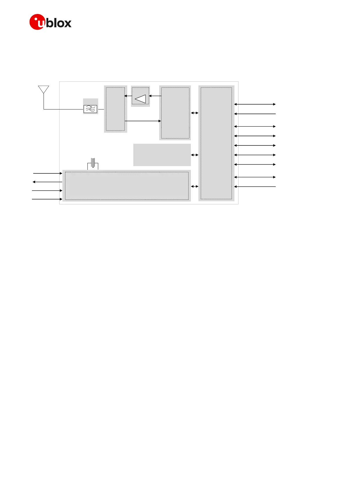
1.2 Architecture
Figure 1 summarizes the internal architecture of SARA-R4/N4 series modules.
Memory
V_INT
RF
transceiver
Cellular
BaseBand
Processor
ANT
VCC (Supply)
USB
DDC (I
2
C)
SIM card det ection
SIM
UART
Power-On
Reset
GPIOs
Ant enna det ect ion
Switch
PA
19.2 MHz
Power
Management
Filter
SDIO
SPI / Digit al Audio
Figure 1: SARA-R4/N4 series modules simplified block diagram
☞ SARA-R404M-00B and SARA-R410M-01B modules, i.e. the “00” and “01” product versions of the
SARA-R4/N4 series modules, do not support the following interfaces, which should be left unconnected
and should not be driven by external devices:
o DDC (I
2
C) interface
o SDIO interface
o SPI interface
o Digital audio interface
☞ SARA-R410M-02B, SARA-R410M-52B, SARA-R412M-02B and SARA-N410-02B modules, i.e. the “02” and
“52” product versions of the SARA-R4/N4 series modules, do not support the following interfaces, which
should be left unconnected and should not be driven by external devices:
o SDIO interface
o SPI interface
o Digital audio interface
 Loading...


