SARA-R4/N4 series - System Integration Manual
UBX-16029218 - R11 Design-in Page 65 of 157
Constant voltage: when the battery voltage reaches the regulated output voltage, the Battery Charger
IC starts to reduce the current until the charge termination is done. The charging process ends when
the charging current reaches the value configured by an external resistor or when the charging timer
reaches the factory set value.
Using a battery pack with an internal NTC resistor, the Battery Charger IC can monitor the battery
temperature to protect the battery from operating under unsafe thermal conditions.
The Battery Charger IC, as linear charger, is more suitable for applications where the charging source has a
relatively low nominal voltage (~5 V), so that a switching charger is suggested for applications where the
charging source has a relatively high nominal voltage (e.g. ~12 V, see section 2.2.1.7 for the specific design-
in).
C5C3 C6
GND
SARA-R4/N4
52
VCC
53
VCC
51
VCC
USB
Supply
θ
U1
PG
STAT2
STA1
VDD
C1
5V0
THERM
Vss
Vbat
Li-Ion/Li-Pol
Bat t ery Pack
D1
B1
C2
Li-Ion/Li-Polymer
Bat t ery Charger IC
D2
PROG
R1
C4
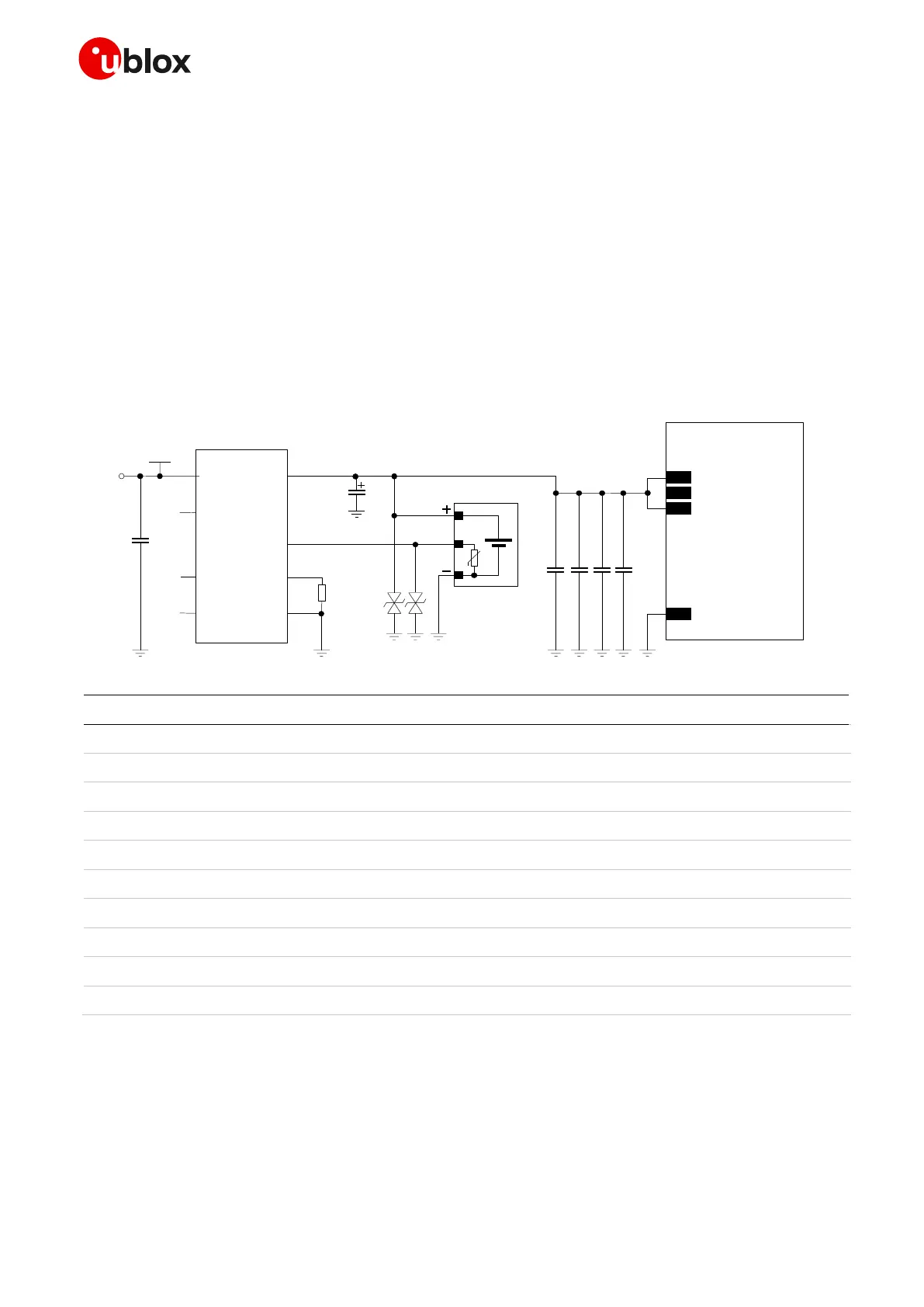
Figure 22: Li-Ion (or Li-Polymer) battery charging application circuit
Part Number - Manufacturer
Li-Ion (or Li-Polymer) battery pack with 470 NTC
1 µF Capacitor Ceramic X7R 16 V
100 µF Capacitor Tantalum B_SIZE 20% 6.3V 15m
T520B107M006ATE015 – Kemet
15 pF Capacitor Ceramic C0G 0402 5% 50 V
GRM1555C1H150JA01 - Murata
68 pF Capacitor Ceramic C0G 0402 5% 50 V
GRM1555C1H680JA01 - Murata
10 nF Capacitor Ceramic X7R 0402 10% 16 V
GRM155R71C103KA01 - Murata
100 nF Capacitor Ceramic X7R 0402 10% 16 V
GRM155R71C104KA01 - Murata
Low Capacitance ESD Protection
Single Cell Li-Ion (or Li-Polymer) Battery Charger IC
Table 15: Suggested components for the Li-Ion (or Li-Polymer) battery charging application circuit
☞ See the section 2.2.1.10, and in particular Figure 27 / Table 19, for the parts recommended to be
provided if the application device integrates an internal antenna.
 Loading...


