SARA-R4 series - System integration manual
UBX-16029218 - R20 System description Page 36 of 128
C1-Public
SARA-R422, SARA-R422S, SARA-R422M8S modules include a secondary auxiliary UART interface
(UART AUX) for communication with an application host processor, supporting AT commands, data
communication, GNSS tunneling
, FW update by means of FOAT, with settings configurable by
dedicated AT commands (for more details, see the SARA-R4 series AT commands manual [2]):
• 4-wire serial port with RS-232 functionality conforming to ITU-T V.24 recommendation [7], with
CMOS compatible signal levels (0 V for low data bit / ON state, 1.8 V for high data bit / OFF state)
o Data lines (DCD as data output, DTR as data input)
o HW flow control lines (RI as flow control output, DSR as flow control input)
• The default baud rate is 115’200 b/s
• The default frame format is 8N1 (8 data bits, no parity, 1 stop bit)
SARA-R4 series modules’ UART interface is by default configured in AT command mode, if the USB
interface is not enabled as AT command / data communication interface (UART and USB cannot be
concurrently used for this purpose): the module waits for AT command instructions and interprets all
the characters received as commands to execute. All the functionalities supported by SARA-R4 series
modules can be in general set and configured by AT commands:
• AT commands according to 3GPP TS 27.007 [8], 3GPP TS 27.005 [9], 3GPP TS 27.010 [10]
• u-blox AT commands (see the SARA-R4 series AT commands manual [2])
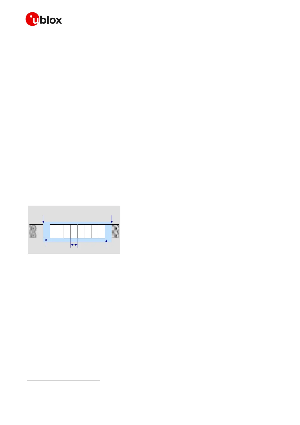
The default baud rate is 115200 b/s, while the default frame format is 8N1 (8 data bits, No parity, 1
stop bit: see Figure 18). Baud rates can be configured by AT command (see the SARA-R4 series AT
commands manual [2]).
☞ Automatic baud rate detection and automatic frame format recognition are not supported.
Figure 18: Description of UART 8N1 frame format (8 data bits, no parity, 1 stop bit)
1.9.1.2 UART signals behavior
At the end of the module boot sequence (see Figure 14), the module is by default in active mode, and
the UART interface is initialized and enabled as AT commands interface only if the USB interface is
not enabled as AT command / data communication interface: UART and USB cannot be concurrently
used for this purpose.
The configuration and behavior of the UART signals after the boot sequence are described below:
• The module data output line (RXD) is set by default to the OFF state (high level) at UART
initialization. The module holds RXD in the OFF state until the module transmits some data.
• The module data input line (TXD) is assumed to be controlled by the external host once UART is
initialized and if UART is used in the application. The TXD data input line has an internal active
pull-down enabled on the SARA-R410M-02B product version, and an internal active pull-up
enabled on the other product version of SARA-R4 series modules.
 Loading...


