SARA-R4 series - System integration manual
UBX-16029218 - R20 Design-in Page 48 of 128
C1-Public
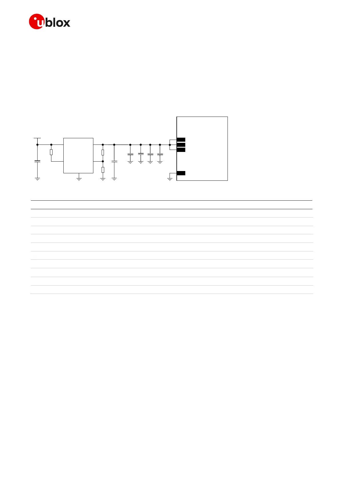
Figure 24 and the components listed in Table 14 show an example of a high reliability power supply
circuit for SARA-R410M modules, which do not support the 2G radio access technology, where the
module VCC is supplied by an LDO linear regulator capable of delivering maximum peak / pulse current
specified for LTE use-case, with suitable power handling capability.
It is recommended to configure the LDO linear regulator to generate a voltage supply value slightly
below the maximum limit of the module VCC normal operating range (e.g. ~4.1 V for the VCC, as in
the circuits described in Figure 24 and Table 14). This reduces the power on the linear regulator and
improves the thermal design of the circuit.
5V
C1
R1
IN OUT
ADJ
GND
5
8
1
3
4
C2
R2
R3
U1
EN
SARA-R410M
52
VCC
53
VCC
51
VCC
GND
C4
C3 C5 C6
Figure 24: Example of high reliability VCC supply circuit for SARA-R410M, using an LDO linear regulator
Part Number - Manufacturer
1 µF Capacitor Ceramic X5R 6.3 V
22 µF Capacitor Ceramic X5R 25 V
100 nF Capacitor Ceramic X7R 16 V
GRM155R71C104KA01 - Murata
10 nF Capacitor Ceramic X7R 16 V
GRM155R71C103KA01 - Murata
68 pF Capacitor Ceramic C0G 0402 5% 50 V
GRM1555C1E680JA01 - Murata
15 pF Capacitor Ceramic C0G 0402 5% 50 V
GRM1555C1E150JA01 - Murata
LDO Linear Regulator 1.0 A
AP7361 – Diodes Incorporated
Table 14: Components for high reliability VCC supply circuit for SARA-R410M, using an LDO linear regulator
☞ See the section 2.2.1.10, and in particular Figure 31 / Table 20, for the parts recommended to be
provided if the application device integrates an internal antenna.
 Loading...


