SARA-R4 series - System integration manual
UBX-16029218 - R20 Design-in Page 93 of 128
C1-Public
Connection with u-blox 3.0 V GNSS receivers
☞ Dedicated AT commands for external u-blox GNSS receiver communication and control are not
supported by SARA-R422 or SARA-R422M8S product versions.
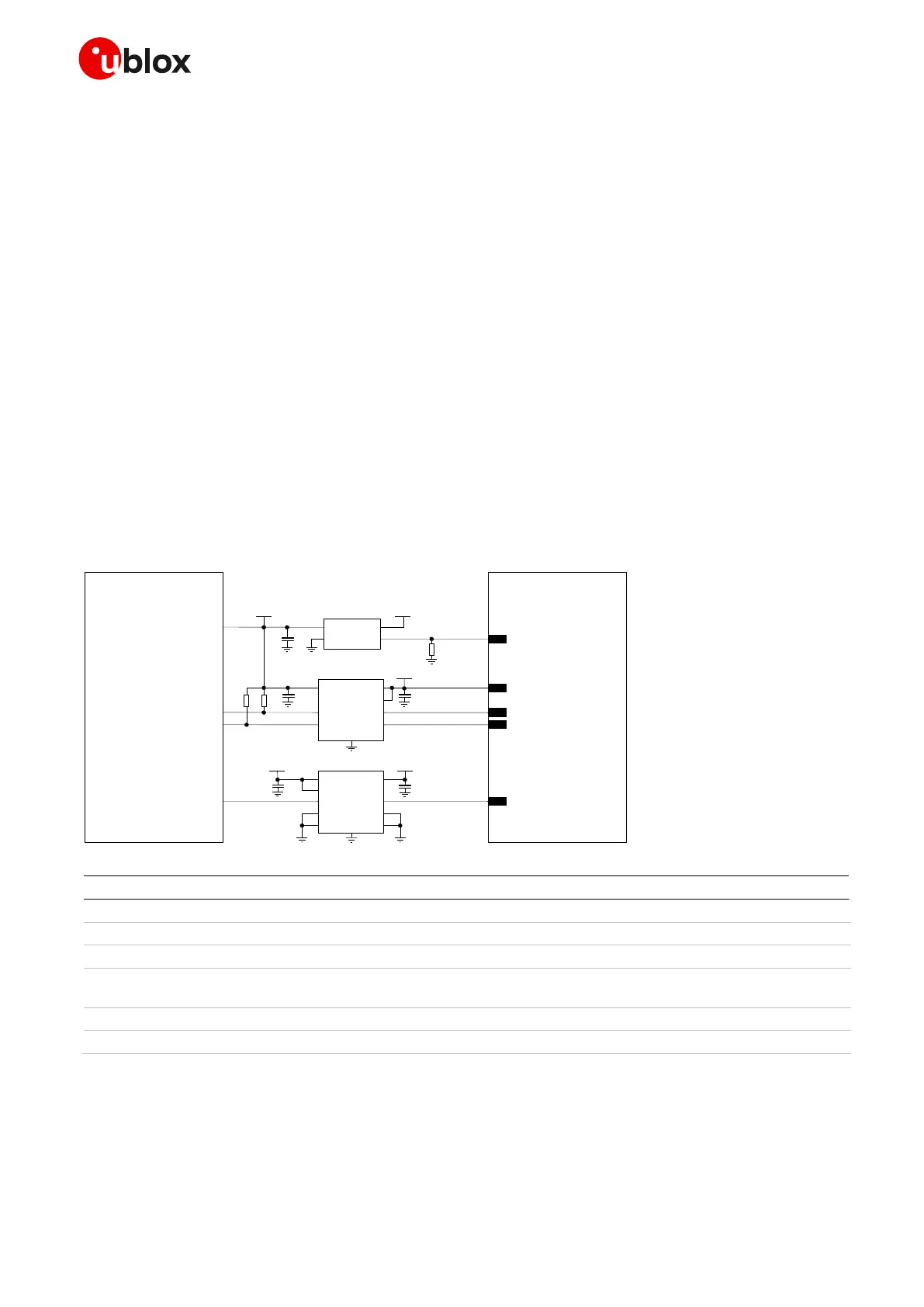
Figure 64 shows an application circuit for connecting the cellular module to an external u-blox 3.0 V
GNSS receiver:
• As the SDA and SCL pins of the cellular module are not tolerant up to 3.0 V, the connection to the
related I2C pins of the u-blox 3.0 V GNSS receiver must be provided using a suitable I2C-bus
Bidirectional Voltage Translator (e.g. TI TCA9406, which additionally provides the partial power
down feature so that the GNSS 3.0 V supply can be ramped up before the V_INT 1.8 V cellular
supply). External pull-up resistors are not needed on the cellular module side, as they are already
integrated in the cellular module.
• The GPIO2 is connected to the active-high enable pin of the voltage regulator that supplies the u-
blox 3.0 V GNSS receiver providing the “GNSS supply enable” function. A pull-down resistor is
provided to avoid a switch on of the positioning receiver when the cellular module is switched off
or in the reset state.
• The GPIO3 pin is connected to the TXD1 pin of the u-blox 3.0 V GNSS receiver providing the
additional “GNSS Tx data ready” function, using a suitable Unidirectional General Purpose Voltage
Translator (e.g. TI SN74AVC2T245, which additionally provides the partial power down feature so
that the 3.0 V GNSS supply can be also ramped up before the V_INT 1.8 V cellular supply.
Table 45: Components for connecting SARA-R4 series modules to u-blox 3.0 V GNSS receivers
☞ For additional guidelines regarding the design of applications with u-blox 1.8 V GNSS receivers,
see the Hardware Integration Manual of the u-blox GNSS receivers.
☞ For additional guidelines regarding Celluar and GNSS RF coexistence, see section 2.4.4
 Loading...


