SARA-R4 series - System integration manual
UBX-16029218 - R20 Design-in Page 92 of 128
C1-Public
Connection with u-blox 1.8 V GNSS receivers
☞ Dedicated AT commands for external u-blox GNSS receiver communication and control are not
supported by SARA-R422 or SARA-R422M8S product versions.
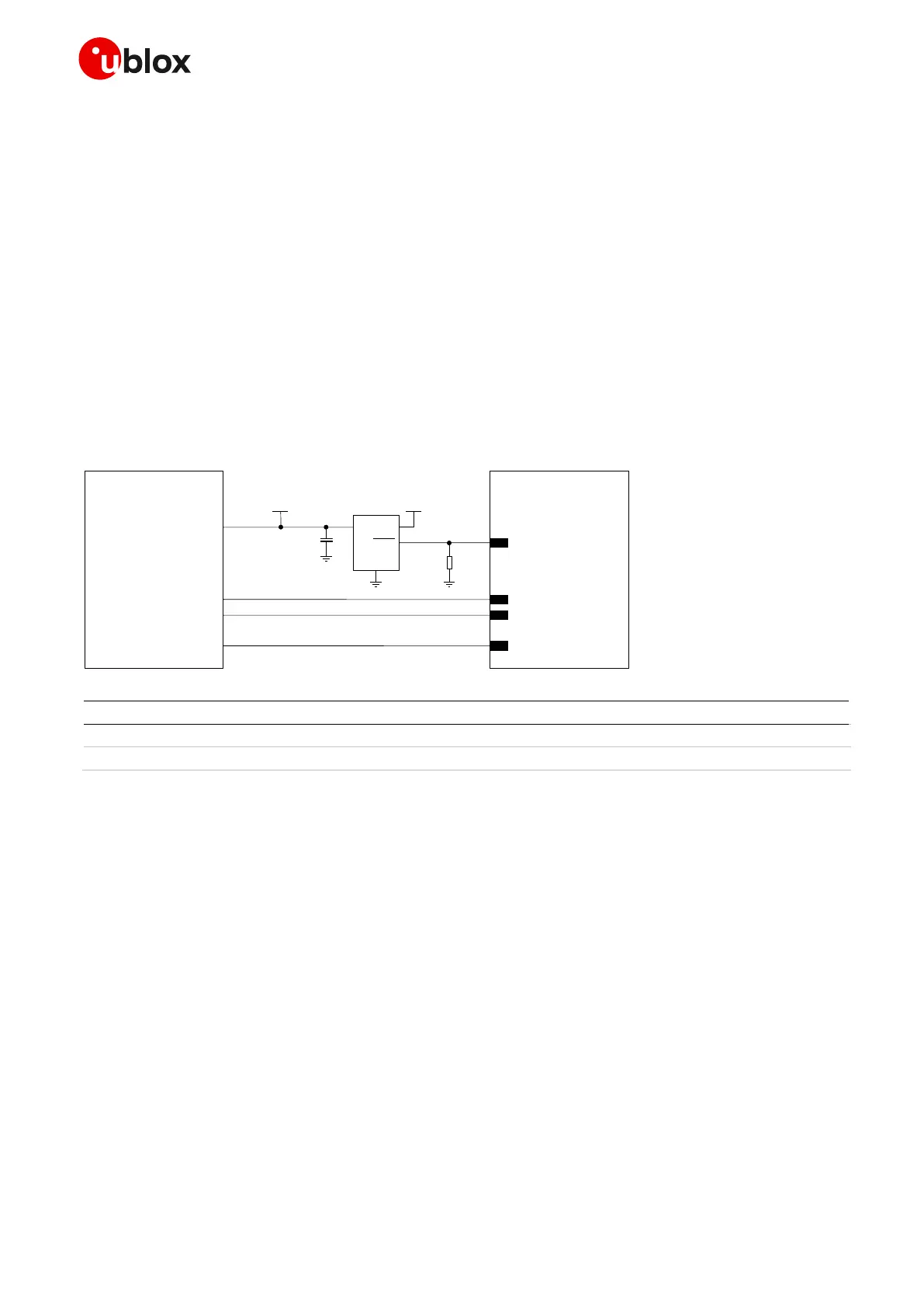
Figure 63 shows an application circuit for connecting the cellular module to an external u-blox 1.8 V
GNSS receiver:
• The SDA and SCL pins of the cellular module are directly connected to the related pins of the u-
blox 1.8 V GNSS receiver. External pull-up resistors are not needed, as they are already integrated
in the cellular module.
• The GPIO2 pin is connected to the active-high enable pin of the voltage regulator that supplies the
u-blox 1.8 V GNSS receiver providing the “GNSS supply enable” function. A pull-down resistor is
provided to avoid a switch on of the positioning receiver when the cellular module is switched off
or in the reset state.
• The GPIO3 pin is connected to the TXD1 pin of the u-blox 1.8 V GNSS receiver providing the
additional “GNSS Tx data ready” function.
Table 44: Components for connecting SARA-R4 series modules to u-blox 1.8 V GNSS receivers
☞ For additional guidelines regarding the design of applications with u-blox 1.8 V GNSS receivers,
see the Hardware Integration Manual of the u-blox GNSS receivers.
☞ For additional guidelines regarding cellular and GNSS RF coexistence, see section 2.4.4
 Loading...


