Eingangsempfindlichkeit
manuelle
Aussteuerung
Mikrofon
0,16 mV, max. 300 mV
Radio
1,8
mV, max. 600 mV
Phono I
80 mV, max.
7 V
Phono II
250 mV, max. 25V
automatische
Aussteuerung
Mikrofon
0,45 mV, max. 17 mV
Radio
2,5
mV, max. 80 mV
Phono I
40 mV. max. 2,2
V
Phono II
keine automatische
Aussteuerung
an diesem Eingang
möglich
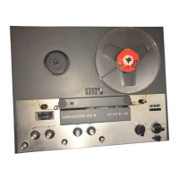
2.8
Prüfung der Aussteuerungs-
automatik A 502
Zur Prüfung und Einstellung muß die Aus-
steuerungsautomatik A 502 in ein einwand-
frei arbeitendes Gerät UHER Variocord 263
Stereo eingebaut sein. Der Regelwiderstand
R 217 wird wie folgt eingestellt:
Zweispurkopfträger Z336 aufsetzen oder
Brücke einlöten zwischen Kontakt 13 und 9
der Aussteuerungsautomatik A502 (Brücke
nach Einstellung wieder entfernen). Gerät
auf Aufnahme „Stereo" schalten und Taste
„
Automatic" drücken. .
Tongenerator an die Kontakte 3 und 2 der
Buchse „Mikro I" anschließen und 15 mV/
1
000 Hz einspeisen. NF-Voltmeter an den
Kontakt 41 der Aufnahmetaste anschließen.
Einstellwiderstand R217 so einstellen, daß
das NF-Voltmeter ca. 2,5 V anzeigt. Jetzt wird
der Einstellwiderstand R217 so weit ver-
dreht, bis die Ausgangsspannung sprunghaft
ansteigt.
Einstellwiderstand
R217 ca. 10°
zurückdrehen.
Die Prüfung der Regelzeit muß mit einem
Vierspurkopfträger Z338 erfolgen.
Tongenerator an die Kontakte 3 und 2 der
Buchse „Mikrofon]" und NF-Voltmeter an
den Kontakt 41 der Aufnahmetaste anschlie-
ßen. Ausgangsspannung des Tongenerators
1
5 mV/1000
Hz.
Mit manueller Aussteuerung Regler „Pegel I"
so weit nach rechts drehen, bis das NF-Volt-
meter 1,5 mV anzeigt. Taste „Automatic"
drücken. Aussteuerung darf sich um -2 dB,
ändern.
Ausgangsspannung des Tongenerators um
20 dB verringern. Nach, 12 sec ± 5 sec muß
wieder Vollaussteuerung, Toleranz
-2 dB,
erreicht sein.
Messung sinngemäß am rechten Kanal wie-
derholen.
Dabei wird der Tongenerator an
die
Kontakte 3 und 2 der Buchse „Mikro-
fon II" und das NF-Voltmeter an den Kon-
takt 50 der Aufnahmetaste angeschlossen.
Tongenerator an die Kontakte 1/4 (parallel
schalten) und 2 der Buchse „Radio" anschlie-
ßen und 80 mV/1000 Hz einspeisen. NF-Volt-
meter zur Messung des linken Kanals am
Kontakt 41, zur Messung des rechten Kanals
I
nput sensitivity
manual level control
Microphone
0.16 mV, 300 mV max.
Radio
1.8
mV, 600 mV max.
Phono I
80 mV,
7 mV max.
Phono II
250 mV,
25V
max.
automatic level control
Microphone
0.45 mV, 17 mV max.
Radio
2.5
mV, 80 mV max.
Phono I
40 mV, 2.2 V
max.
Phono II
no facility for automatic
recording level control
at this input.
2.8
Checking the Automatic Recording
l
evel control A 502
For testing and adjusting, the automatic level
control A 502 must built into a properly work-
i
ng UHER Variocord 263 Stereo tape record-
er. The regulating resistor R 217 is adjusted
as follows:
Place the two-track head support Z 336 in
position or alternatively solder bridge piece
between contacts 13 and 9 of automatic level
control A 502 (remove bridge piece after the
adjustment).
Set the unit to Recording
"stereo" and press pushbutton "Automatic".
Connect audio oscillator to contacts 3 and 2
of socket "Micro I" and feed in 15 mV/
1
000 Hz. Connect LF voltmeter to contact 41
of the recording pushbutton. Set the adjust-
able resistor R 217 in such a manner that the
LF voltmeter indicates approx. 2.5V. Now
the adjustable resistor R217 is turned until
the Output voltage rises suddenly. Turn back
the adjustable resistor R 217 by approx. 10
degrees.
The testing the time of control must be made
with a four-track head support Z 338.
Connect audio oscillator to contacts 3 and 2
of socket "Microphone I" and LF voltmeter to
contact 41 of the recording push-button.
Output voltage of the audio oscillator 15 mV/
1
000 Hz.
Using the manual level control "Level I°, turn
the control clockwise until the LF voltmeter
i
ndicates 1.5 mV. Press pushbutton "Auto-
matic". Level control may vary by -2 dB.
Reduce output voltage of audio oscillator by
20 dB. After 12 sec ± 5 sec, maximum re-
cording level, with a tolerance of -2 dB,
must be reached once more.
Repeat measurement logically at the right-
hand channel. Here, the audio oscillator is
connected to contacts 3 and 2 of socket
"
Microphone IV and the LF voltmeter to con-
tact 50 of the recording pushbutton.
Connect audio oscillator to contacts 1/4
(connect in parallel) and 2 of socket "Radio"
and feed in 80 mV/1000 Hz. Connect LF volt-
meter for measuring the left-hand channel
to contact 41, for measuring the right-hand
Sensibilite d'entree
Röglage du niveau
d'enregistrement manuel
Microphone
0,16 mV- max. 300 mV
Radio
1,8
mV - max. 600 mV
Phono I
80 mV-max.
7 V
Phono II
250 mV -max. 25V
Röglaje du niveau
d'enregistrement autom.
Microphone
0,45 mV-max. 17 mV
Radio
2,5
mV-max. 80 mV
Phono I
40 mV - max. 2,2 V
Phono II
un reglage automatique
du niveau d'enregistre-
ment West pas possible
ä cette entree
2.8
Contröle du systeme de reglage automa-
tique du niveau d'enregistrement A 502
Pour son contröle et son ajustage, le systäme
de reglage automatique A502 doit ätre in-
corpore dans un magnötophone UHER Vario-
cord 263 Stereo en parfait ätat de fonction-
nement. Ajuster le potentiomätre R 217 de
l
a fagon suivante:
Monter une unite de tetes magnötiques .4
pistesn
type Z 336 ou souder un pont entre
l
es contacts 13 et 9 du systäme de reglage
automatique A 502 (ce pont äst ä supprimer
apräs les opärations d'ajustage). Enclencher
l
e
magn6tophone en regime -Enregistre-
ment - stereo= et enfoncer la touche «Auto-
matique».
Brancher un generateur BF surles contacts
3 et 2 de la prise «Micro I= et appliquer un
signal de 1000 Hz ä 15 mV. Raccorder un
voltmätre ä lampe BF sur le contact 41 de
l
a touche «Enregistrementn. Ajuster le po-
tentiomätre R 217 de fagon que la voltmätre
i
ndique une valeur de 2.5V. Regler ensuite
l
e potentiomätre R 217 pour que la tension
de sortie s'accroisse brusquement, puis le
mancauvrer dans le sens contraire d'un angle
d'environ 10°.
Le contröle du temps de correction doit ötre
executö avec une unite de tötes magnötiques
«4 pistes= type Z338.
Brancher un generateur BF sur les contacts
3 et 2 de la prise «Microphone I= et appliquer
un signal de 1000 Hz ä 15 mV. Raccorder un
voltmätre ä lampe BF sur le contact 41 de la
touche «Enregistrement=.
Manceuvrervers la droite le bouton du rägleur
«Niveau 1-, jusqu'ä ce que voltmätre indique
une valeur de 1,5 mV. Enfoncer la touche
«Automatique». Le niveau (1,5 mV) indique
par le voltmätre ne doit pas varier de plus
de -2 dB.
Diminuer de 20 dB le niveau de sortie du
generateur BF. Apräs 12 sec. ± 5 sec., le
niveau
maximal d'enregistrement doit ötre
rötabli (tolerance
-2 dB).
Reprendre la möme mesure pour le canal de
droite.
A cet effect, brancher le generateur
BF sur les contacts 3 et 2 de la prise «Micro-
phone II= et raccorder le voltmätre BF sur
1
8