Co. LTD
M24020100321EN
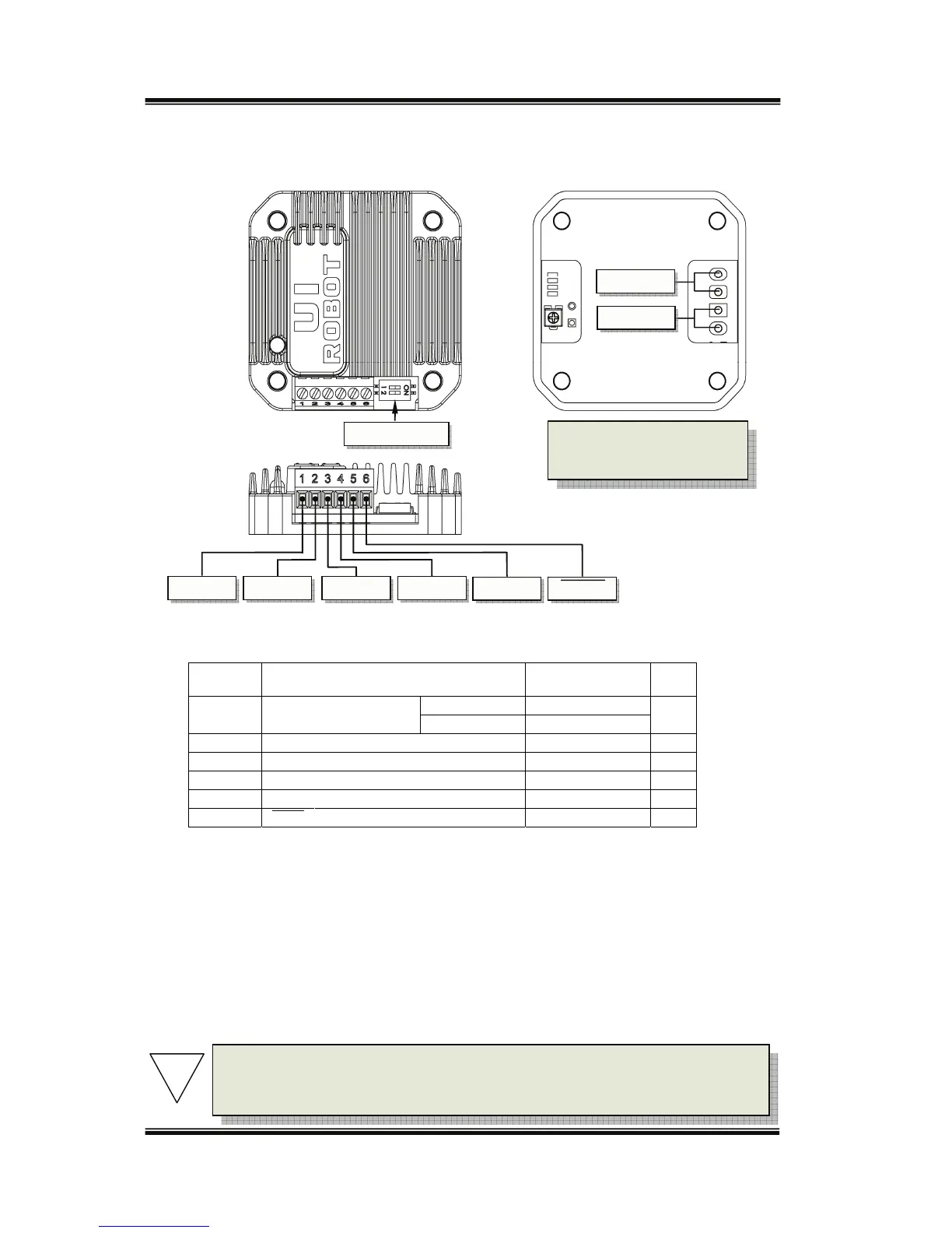
Terminal Description
Screw Terminals
Terminal
No./Color
Description MINNOMMAX UNIT
1/Red V+ Supplyvoltage
UIM24004‐8 12 40
VDC
UIM240021035
2/Black GND Supplyvoltageground 0 VDC
3/White Vcc Opto‐couplercommonanode 5
(1)
VDC
4/Green DIR Directioninput
(2)
GND Vcc VDC
5/Blue STEP Steppingpulseinput
(3)
GND Vcc VDC
6/Yellow SHDN Shutdownthecontroller
(4)
GND Vcc VDC
Note:
(1) Pleasereferto“opticallyisolatedinputinterface”sectionfordetails.
(2) Inputisconsideredhighlevelifthisterminalisnotconnected.
(3) Low‐levelpulsedurationshould>8μs.Maximumpulsefrequencyis50KHz.
(4) Anactivelow‐levelinputshutsdownpowersupplytothe
motor.High‐levelinputorleftopenmakesthe
controllerfullyworking.Whenawakenfromshutdownmode,wait1millisecondbeforesendingpulse.
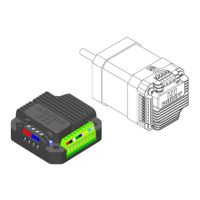
Motor Wiring Pads
Pad A + / A- (at the bottom of the controller): Connect to the stepper motor phase A
Pad B + / B- (at the bottom of the controller): Connect to the stepper motor phase B
DIP Switch
GND Vcc DIR
V+
Phase B
Phase A
B- B+ A+ A-
STEP SHDN
To avoid loss of terminal
screws, please always keep
screwstightened.
Note: To avoid damaging the controller, make sure the phase winds are
connectedcorrectly.Resistancebetweendifferentphases’leadsisusually>
100KΩ.Resistancebetweendifferentphases’leadsisusually<100Ω.
!