Co. LTD
M24020100321EN
Typical Application
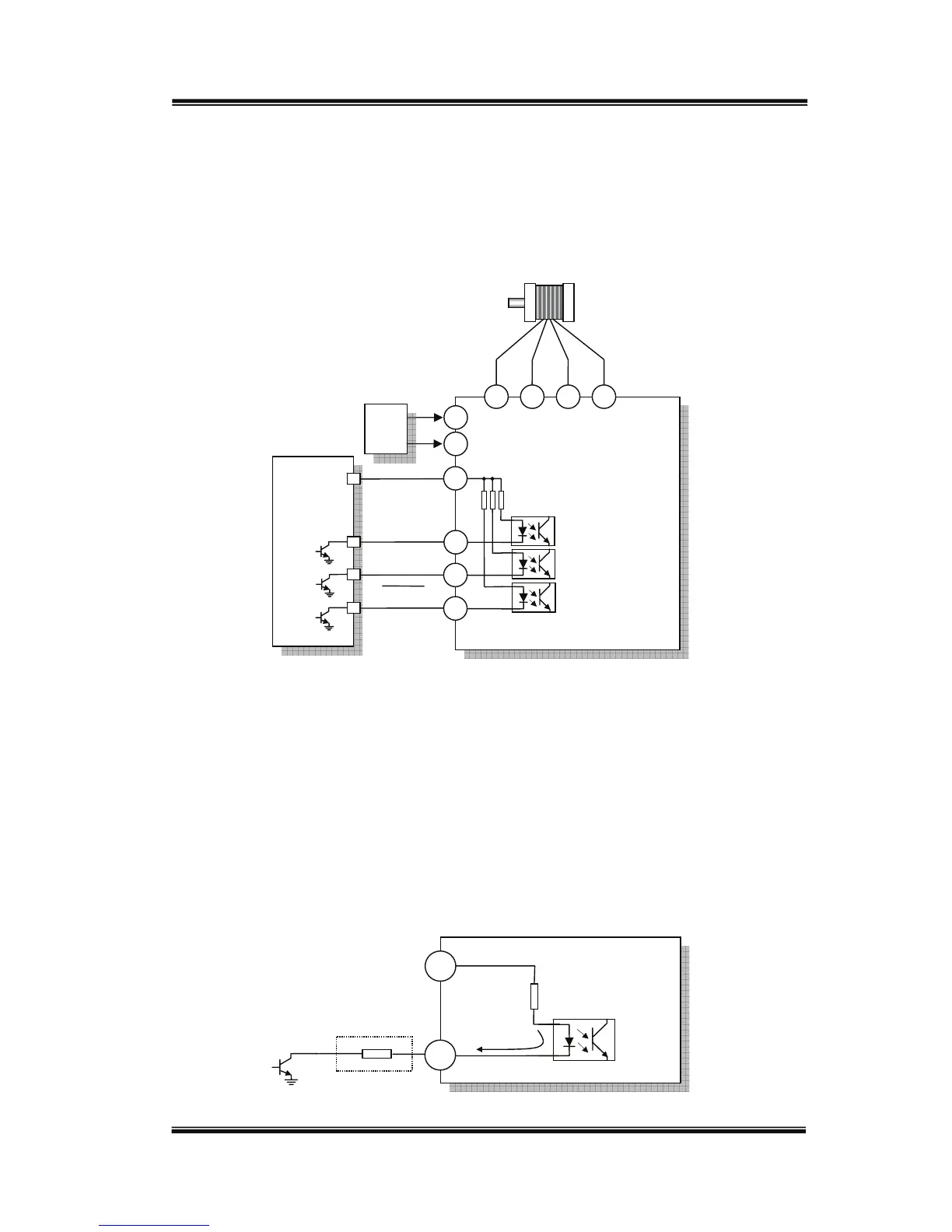
UIM240xx controller’s wiring is very straightforward as shown in following Figure.
Terminal 6 (SHDN) can be left open if offline is not needed.
Optically Isolated Input Interface
UIM240xx controllers’ logic control inputs are all optically isolated. All opto-couplers
share one common anode (Vcc) as shown in above schematic diagram. Typically, Vcc is
5V. However, 3.3V or voltages higher than 5V are also acceptable, so long as the current
through the opto-coupler’s emitter is between 5~20mA.
Should a voltage higher than 5V be applied to Vcc, an additional resistor is needed for
every terminal to ensure that the current through each emitter does not exceed 20mA.
UIM240xx
Stepper Controller
10~40VDC
StepperMotor
A+ A- B+ B-
1
2
DC+
DC‐
UserDevice
3.3~5V
Direction
Pulse
SHDN
Vcc
5
4
6
3
UIM240xxController
+
‐
Vcc
User
Device
500