EasyManua.ls Logo

UIrobot UIM2501 - User Manual

UIrobot UIM2501
17 pages
Print Icon
To Next Page IconTo Next Page
Loading...
RS2
3
3
2-CA
N
for
U
U
s
N
2.0B
U
IM24
s
e
r
Conv
2XX
M
r
M
a
ertin
g
M
otio
n
a
n
u
UI
g
Cont
n
Cont
u
al
M
2501
roller
roller
Question and Answer IconNeed help?

Do you have a question about the UIrobot UIM2501 and is the answer not in the manual?

Summary

Features

Embedded DSP Microprocessor

High-performance DSP processor enabling advanced control functions.

CAN2.0 B Active Communication

Supports 2-wire, 1Mbps CAN 2.0B for robust, long-distance communication.

RS232 Communication

Provides RS232 three-wire serial communication up to 112500 bps.

Wide Supply Voltage

Operates with a flexible supply voltage range from 6 to 40VDC.

Terminal Description

Screw Terminals Description

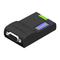
Details screw terminal assignments for power, ground, and CAN signals.

DIP Switch Functions

Explains the 8-bit DIP switch for controller ID and termination resistor settings.

Typical Application

Standalone Operation Wiring

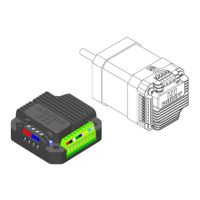
Illustrates the wiring scheme for connecting a single UIM242 controller to the UIM2501.

Network Operation

Network Wiring Solution

Presents a wiring solution for multiple UIM242 controllers in a CAN network.

Product Characteristics

Absolute Maximum Ratings

Lists the stress limits for supply voltage, ambient temperature, and storage conditions.

Electrical Characteristics

Details operating voltage, current consumption, and communication specifications.

Environment Requirements

Specifies operating conditions for temperature, humidity, and vibration resistance.

Size and Weight

Provides the physical dimensions and weight of the UIM2501 controller.

Overview

Instruction and Feedback Structure

Explains how instructions and feedback are handled by the UIM2501 protocol converter.

Motor Control Functions

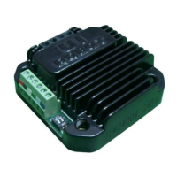
Details how motor control is managed by UIM242 controllers via the UIM2501.

RS232 Communication

RS232 Port Settings

Specifies the required RS232 port settings: 8 data bits, 1 stop bit, no parity.

Hand-Shaking Procedure

Describes the handshake method for verifying controller existence and firmware version.

Baud Rate Configuration

Baud Rate Change Instruction

Details the BDR instruction to change the RS232 baud rate and store it in EEPROM.

Reset Baud Rate to Factory Default

Provides steps to reset the baud rate to the factory default of 9600 via DIP switch.

Operation Modes

Global Control Introduction

Explains broadcasting commands (global control) to subsidiary UIM242 controllers.

Controller Addressing

Controller ID Assignment Instruction

Details the SETADR instruction for assigning unique IDs to UIM242 controllers.

Object Specify Instruction

Explains the ADR instruction to select a specific UIM242 controller for subsequent commands.

Global Control Instructions

Global Register Instruction

Records the quantity and IDs of all subsidiary UIM242 controllers.

Global Motor Enable Instruction

Enables the H-Bridge of all UIM242XX controllers for motor motion.

Global Motor Disable Instruction

Disables the H-Bridge of all UIM242XX controllers, useful for emergencies.

Global Motor Control Instructions Part 1

Global Motor Current Setup

Sets motor current parameters for all subsidiary UIM242 Controllers.

Global Auto Current Reduction

Enables or disables the ACR function for all UIM242 Controllers.

Global Micro-Stepping Resolution Setup

Sets the micro-stepping resolution for all subsidiary UIM242 Controllers.

Global Direction Instruction

Sets the motion direction for all subsidiary UIM242 Controllers.

Global Speed Setup Instruction

Sets the motor speed parameters for all subsidiary UIM242 Controllers.

Global Motor Control Instructions Part 2

Global Position Control Instruction

Sets relative position control parameters for all subsidiary UIM242 Controllers.

Global Origin Point Setup Instruction

Clears the absolute position counters of all subsidiary UIM242 Controllers.

Appendix A Dimensions

Overview

The UIM2501 RS232-CAN Converting Controller is a device designed to bridge communication between a user's RS232 interface and a CAN bus network, specifically for use with UIM242XX stepper motor controllers. It acts as a protocol converter, simplifying interaction with CAN-based motor control systems.

Function Description:

The primary function of the UIM2501 is to translate RS232-based instructions from a user device into more concise and efficient CAN-based instructions for UIM242XX controllers. Conversely, it converts CAN messages from UIM242XX controllers back into RS232 messages for the user device. This allows users to leverage the advantages of a CAN network, such as long communication distances and high noise immunity, without needing to deal with the complexities of the CAN protocol directly. The UIM2501 also coordinates and controls multiple UIM242XX controllers within the network.

One UIM2501 controller can network with up to 100 UIM242XX controllers. The interface is designed to be simple, intuitive, and fault-tolerant, eliminating the need for users to have extensive knowledge of stepper motor driving or CAN protocol. It supports 1 Mbps CAN communication speed, with all UIM242 instructions typically taking less than 0.1 ms (normally 0.05 ms) to transfer on the bus. On the user side, it supports a maximum RS232 baud rate of 115200 bps.

Important Technical Specifications:

Electrical Characteristics (Ambient Temperature 25℃):

  • Supply Power Voltage: 6V ~ 40VDC
  • Current Consumption: Max 100mA

Communication (Ambient Temperature 25℃):

  • To User Device: RS232
  • Wiring Method: DB9 Female Connector
  • RS232 Baud Rate: MAX 115200 bps
  • To UIM242 Controller: Active CAN 2.0B
  • CAN Wiring Method: 2-Wire, CANH, CANL
  • CAN Bus: Supports 1 Mb/s operation, ISO-11898 standard physical layer requirements, suitable for 12V and 24V systems, and can connect up to 100 nodes.

Absolute Maximum Ratings:

  • Supply Voltage: 6V to 40V
  • Voltage on RX with respect to GND: -25V to +25V
  • Voltage on TX with respect to GND: -13.2V to +13.2V
  • Ambient Temperature Under Bias: -20°C to +85°C
  • Storage Temperature: -50°C to +150°C

Environment Requirements:

  • Cooling: Free Air
  • Environment: Avoid dust, oil mist, and corrosive gases
  • Working Temperature: -20°C ~ +85°C
  • Humidity: <80%RH, no condensation, no frosting
  • Vibration: 3G Max
  • Storage Temperature: -50°C ~ +150°C

Size and Weight:

  • Size: 66.4mm x 38mm x 18mm (LWH)
  • Weight: 0.1 kg

Usage Features:

  • Embedded DSP Microprocessor: Features a high-performance Digital Signal Processor, offering simple, intuitive, and rich instructions, intelligent fault-tolerance, and a user-friendly interface.
  • CAN2.0B Active Communication: Utilizes a 2-wire differential data bus for long-distance operation and high noise immunity.
  • RS232 Communication: Employs three-wire serial communication with a maximum baud rate of 112500 bps.
  • Wide Supply Voltage: Operates on a broad supply voltage range of 6 ~ 40VDC.
  • Compact and Durable Design: The UIM2501 is compact in size, and its enclosure is made of die-cast aluminum, providing rugged protection and improved heat dissipation.
  • DIP Switch for Configuration: An 8-bit DIP switch allows for multiple functions. DIP1-DIP7 are read as the controller's ID/address upon powering up. After power-up, DIP1 and DIP2 are used for RS232-related features. DIP8 enables the built-in terminating resistor.
  • Standalone and Network Operation: Can be used with a single UIM242 controller or integrated into a network with up to 100 UIM242XX controllers.
  • Hand-Shaking: The device supports hand-shaking to verify its existence and firmware version. It issues a greeting message (0xAA 0xAB 0xAC...) upon powering up or receiving the ASCII message "ABC;".
  • Baud Rate Configuration: The factory default baud rate is 9600 bps. Users can change it using the BDR instruction. The new baud rate is stored in EEPROM and takes effect after a restart.
  • Baud Rate Reset: In case the baud rate is forgotten, it can be reset to the factory default of 9600 bps by toggling DIP1 for two rounds within 10 seconds of rebooting.
  • Controller ID Assignment (SETADR): UIM242XX controllers have a factory default ID of 5. Users can assign unique IDs (5 to 126) using the SETADR instruction, ensuring only one UIM242XX controller is connected during the assignment process.
  • Object Specify Instruction (ADR): Before sending motor control instructions to a specific UIM242XX controller in a network, the user must specify its ID using the ADR instruction. All subsequent object-specific instructions will be sent to this specified object until a new ID is specified.
  • Global Control Instructions: The UIM2501 supports broadcasting commands to all subsidiary UIM242XX controllers using global control instructions (e.g., gREG, gENABLE, gOFFLINE, gCUR, gACR, gMCS, gDIR, gSPD, gSTP, gORG). These instructions allow for simultaneous control of multiple motors.
    • gREG (Global Register): Records the quantity and IDs of all subsidiary UIM242 controllers, providing an indicator of network health.
    • gENABLE (Global Motor Enable): Enables the H-Bridge of all UIM242XX controllers, allowing all motors to move after individual motion parameters have been set.
    • gOFFLINE (Global Motor Disable): Disables the H-Bridge of all UIM242XX controllers, useful for emergency shutdowns.
    • gCUR (Global Motor Current Setup): Sets the motor current for all subsidiary UIM242 controllers (0-80).
    • gACR (Global Auto Current Reduction): Enables/disables the ACR function for all subsidiary UIM242 controllers (0 or 1).
    • gMCS (Global Micro-Stepping Resolution Setup): Sets the micro-stepping resolution for all subsidiary UIM242 controllers (1, 2, 4, 16).
    • gDIR (Global Direction): Sets the motion direction for all subsidiary UIM242 controllers (0 or 1).
    • gSPD (Global Speed Setup): Sets the motor speed for all subsidiary UIM242 controllers (0-65535).
    • gSTP (Global Position Control): Sets relative position control for all subsidiary UIM242 controllers (0-2,000,000,000).
    • gORG (Global Origin Point Setup): Clears absolute position counters of all subsidiary UIM242 controllers.
  • Software Support: UI Robot provides free Microsoft Windows XP-based VB/VC demo software and source code to facilitate quick start programming for user devices.

Maintenance Features:

  • Terminating Resistor: For long-distance CAN bus transfers, both ends of the bus should be terminated with 120Ω resistors. The UIM2501 converter has a built-in terminating resistor that can be enabled by toggling DIP8 to the ON position. A resistor is also needed at the UIM242 controller end of the bus.
  • Twisted Wire Pair for CANH/CANL: To achieve optimal communication, the CANH and CANL wires should be a twisted pair.
  • Point-to-Point Wiring Scheme: In multi-node CAN applications, maintaining a direct point-to-point wiring scheme is crucial. A single pair of wires should connect each element of the CAN bus. Star configurations should be avoided to prevent reflections and data errors. If stubs are unavoidable, they should be kept as small as possible.
  • Screw Terminal Maintenance: To prevent loss of terminal screws, it is recommended to always keep them tightened.

UIrobot UIM2501 Specifications

General IconGeneral
BrandUIrobot
ModelUIM2501
CategoryController
LanguageEnglish

Related product manuals