Page|4
UIM2501
UI Robot Technology Co. LTD M25020101008EN
Terminal Description
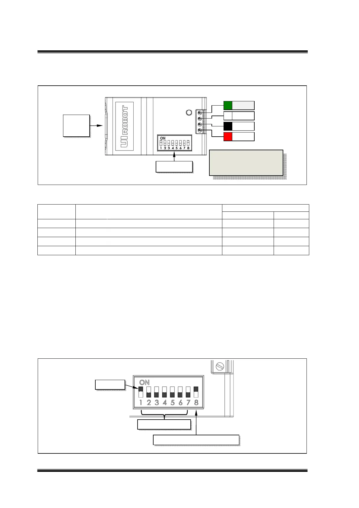
Figure 0-1: Terminal Description
Description of Screw Terminals
Terminal
No. / Color
Description
Input / Output
MIN NOM MAX UNIT
1 / Red V+ Supply voltage 6 40 VDC
2 / Black GND Supply voltage ground 0 VDC
3 / White CANH
CANHigh‐LevelVoltageI/O
VDC
4 / Green CANL
CANLow‐LevelVoltageI/O
VDC
RS232 Connector is a DB-9 (Female Pin) connector.
DIP Switch
UIM2501 controller has an 8-bit DIP switch, which serves multiple functions. When powering up,
DIP1~DIP7 are read as the UIM2501 controller’s ID/address. After powering up, DIP1 and DIP2
are assigned to other RS232 related features (refer to the “RS232 communication” section).
DIP8 is used to enable the built-in terminating resistor.
Unless necessary, please maintain the DIP positions as shown in following Figure.
Figure 0-2: Terminal Description
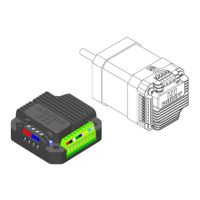
Actuator
Controller ID
Terminating Resistor Enable
V+
GND
CANH
CANL
RS232
DB9
DIP Switch
To avoid loss of terminal
screws, please always
keep screws tightened.