Page|5
UIM2501 Converting Controller
M25020101008EN UI Robot Technology Co. LTD
Typical Application
Standalone Operation
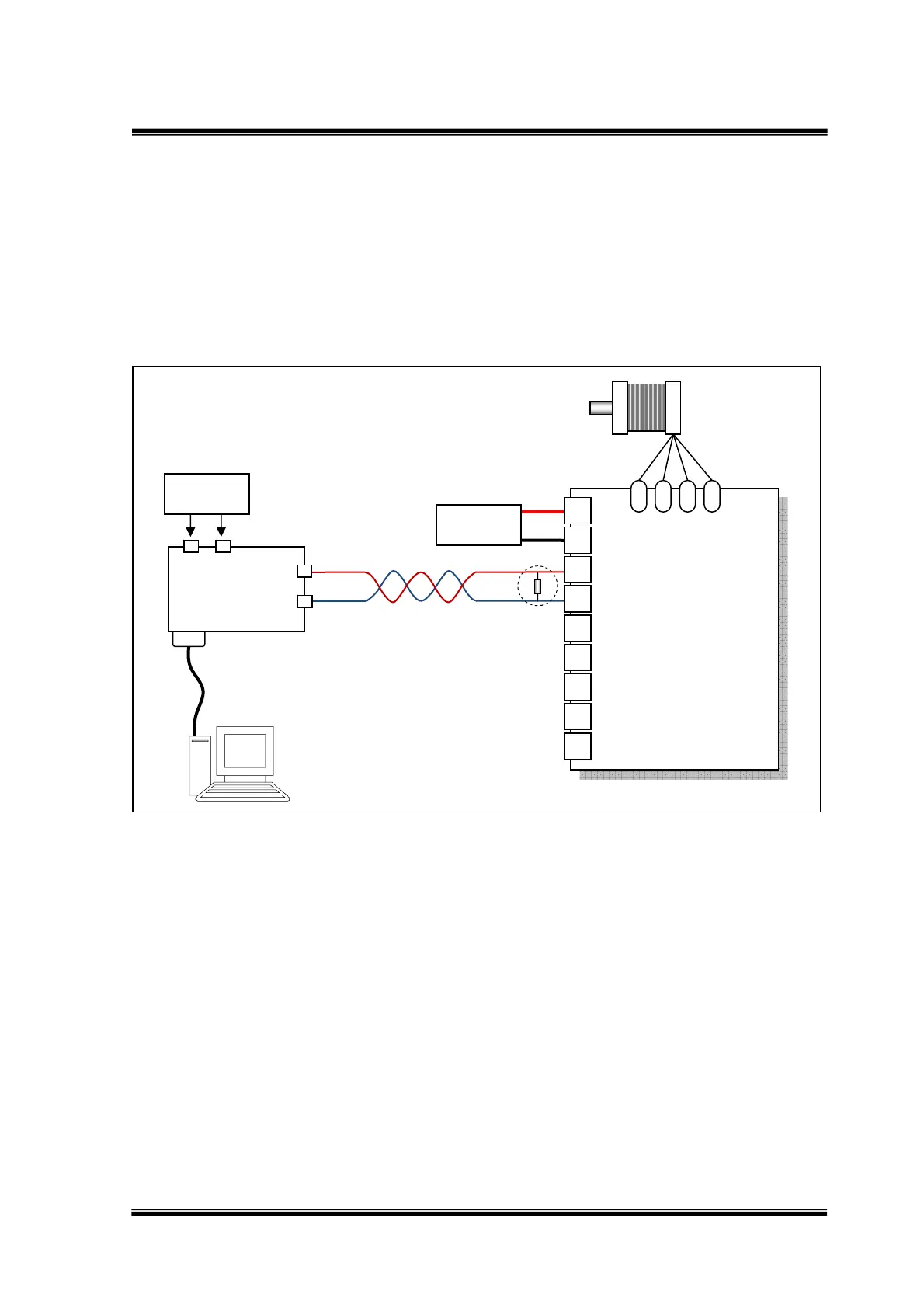
When only one UIM242 controller is needed, user can use the following wiring scheme.
Please note that, the standalone wiring scheme is mandatory when assigning a controller ID
to a UIM242 controller (motor is not required). For details, please refer to section 3.1.
Figure 0-3: Wiring Scheme for Standalone Operation
Notice:
For long distance transfer, both ends of the bus should be terminated with120Ω terminating
resistors. UIM2501 converter already has a build-in terminating resistor. To enable it, user
needs toggle the DIP8 to the ON position. On the UIM242 controller side, user needs to
attach a resistor to the end of the bus as shown in above figure 0-3.
To achieve the best communication, CANH and CANL should be a twisted wire pair.
UIM2501
Controller
CANL
RS232 Cable
DB9Port
1 2
3
4
CANH
120Ω
12‐40V
DCSupply
UIM242XX
Controller
1
2
3
4
5
7
8
6
A+ A- B- B+
CANL
CANH
V+
GND
G
S1
S2
S3
9
P4
6–40V
DCSupply
TwistWirePair
StepperMotor