Page|6
UIM2501
UI Robot Technology Co. LTD M25020101008EN
Network Operation
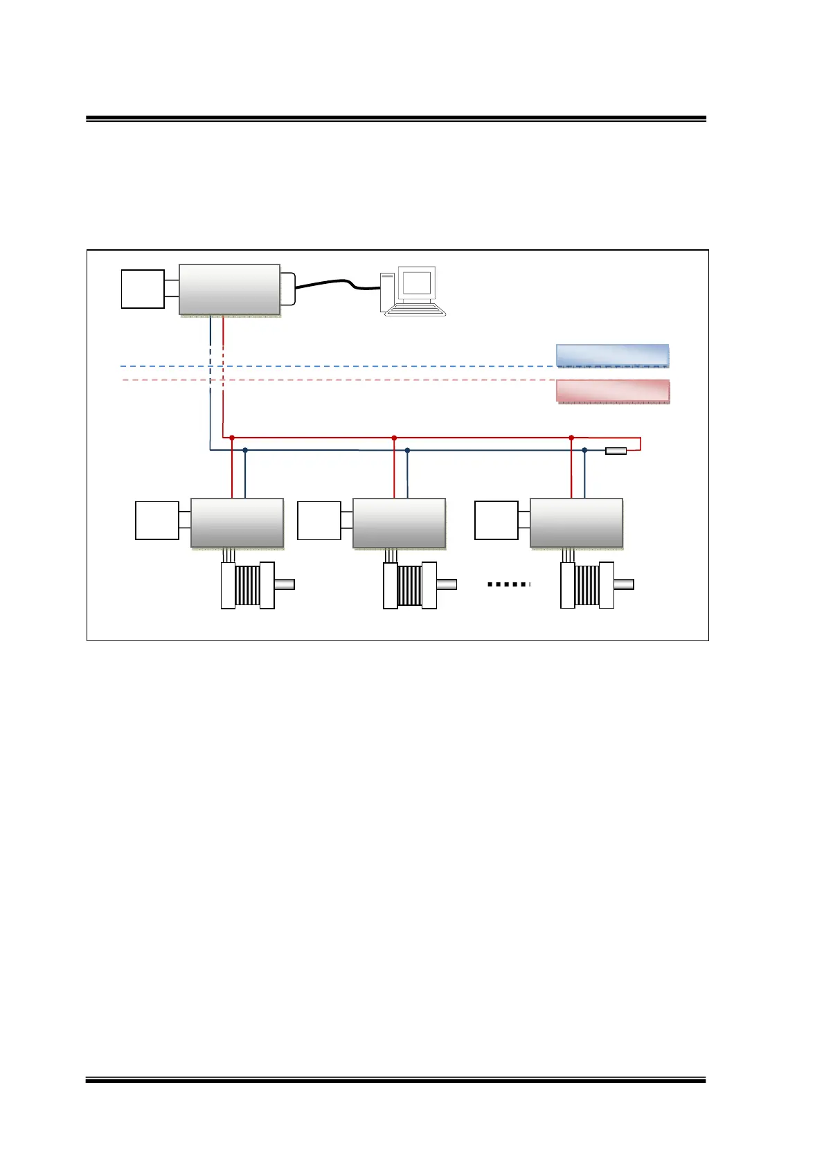
Multiple UIM242XX controllers can be wired together to form a reliable motor network.
Following figure provides a typical network wiring solution.
Figure 0-4: Wiring Scheme for Network Operation
Notice:
In multi-node CAN applications, it is important to maintain a direct point-to-point wiring
scheme. A single pair of wires should connect each element of the CAN bus, and the two
ends of the bus should be terminated with 120Ω resistors. A star configuration should never
be used.
UIM2501 converter has a build-in terminal resistor. To enable the UIM2501 converter’s
terminating resistor, please toggle the DIP8 to ON position. User only needs to attach a
resistor at the UIM242 end of the bus.
In addition, any deviation from the point-to-point wiring scheme creates a stub. The high-
speed edge of the CAN data on a stub can create reflections back down the bus. These
reflections can cause data errors by eroding the noise margin of the system. Although stubs
are unavoidable in a multi-node system, care should be taken to keep these stubs as small
as possible.
RS232
Motor#1
6‐40
VDC
Power
CANH
CANL
CANH
CANL
120Ohm
CANH
CANL
Factory
ControlRoom
UIM250
Controller
12‐40
VDC
Power
UIM242xx
Controller1
Motor#2
CANH
CANL
12‐40
VDC
Power
UIM242xx
Controller1
Motor#100
CANH
CANL
12‐40
VDC
Power
UIM242xx
Controller1