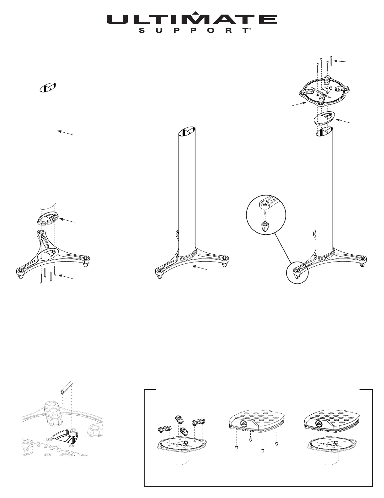
Place one of the decouplers on one of
the ends of the column. Make sure the
two large holes on the decoupler line up
with the two channels of the column.
The third channel should be covered.
Line up screw holes on the decoupler
with the tripod base and attach using
four M6 x 50mm socket head
cap screws.
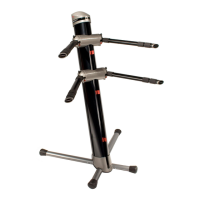
OPTIONAL CONFIGURATION (SOLD SEPARATELY)
Combine the MS-80B to the MS-90, then be able to adjust angle and axis of your speakers.
MS-90/36 and MS-90/45
Assembly Instructions
Remove the four rubber
decouplers from the MS-90
top plate.
Remove the four rubber feet
from the MS-80B.
Place the MS-80B on the top
plate of the MS-90. Spikes will
t in pin holes.
Users planning to add extra weight to
their stand with sand or shot should
do so prior to adding the second
decoupler. We recommend using
small bags to add the sand to avoid
unwanted spillage. Add to the large
channel of the stand. The two smaller
channels are for cables and should
remain open.
Place web cover over the wall
separating the two channels.
Place second decoupler on top of
column, line up the two large holes
again with the column channels. Place
monitor stand top plate on decoupler.
Center hole on top plate should line up
with the two channels. Attach using
four M6 x 50mm socket head
cap screws.
M6 x 50mm
Socket head
cap screw
M6 x 50mm
Socket head
cap screw
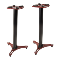
Top Plate
3 Channel
Column
Tripod Base
Decoupler
Decoupler
To use spikes twist
back and forth, while
pulling, on rubber
feet until removed.