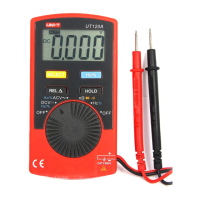
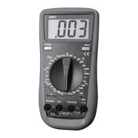
UT131A/B/C/D
I.Overview
I .I Open Box Inspection
I .Safe Operation RuleII
IV. Electrical Symbols
Warning
VI.Structure (see Figure 1)
Figure 1
Capacitance
Red Black Red Black
Figure 2bFigure 2a
Red Black
Figure 3
Figure 4
Red Black
Palm Size Multimeter
User Manual
The new generation UT131 series products redefine the performance
standards for entry-level digital multimeter. The innovative industrial design
ensures the products have 2 meters impact resistance. The new LCD display
layout provides a clear display for better user experience. The UT131 series
ensure safe operation in CAT II 250 V environment.
The special features of each model are as follows:
UT131A: 2mF capacitance test function
UT131B: Battery test with status indicators
UT131C: Temperature test
UT131D: NCV test
Open the package box and take out the device. Please check whether the
following items are deficient or damaged and contact your supplier immediately
if they are.
User manual ----------------------- 1 pcs
Test leads ---------------------------1 pair
Protective case---------------------1 pcs
K-type thermocouple -------------1 pcs (UT131 only)
Warning:
Please carefully read “Safe Operation Rule” before using the device.
1). Safety certification
This device strictly follows the CE standards: EN 61010-1: 2010,
EN 61010-2-030:2010, EN 61326:2013, as well as CAT II: 250V, RoHS,
pollution grade II, and double insulation standards.
2). Safety instructions and precautions
1. Do not use the device if the device or test leads appear damaged or if
you suspect that the device is not operating properly. Pay particular
attention to the insulation layers.
2 If the test leads are damaged, it must be replaced with one of the same .
type or the same electrical specification.
3 When measuring, do not touch exposed wires, connectors, unused inputs, .
or the circuit being measured.
4 When measuring the voltage higher than 60 VDC or 30 VACrms, keep .
your fingers behind the finger guard on the test lead in order to prevent
electric shock.
5 If the range of the voltage to be measured is unknown, the maximum range .
should be selected and then gradually decreased.
6 Never input voltage and current exceeding the value listed on the device..
7 Before switching ranges, make sure to disconnect the test leads with the .
circuit to be tested. It is strictly prohibited to switch the ranges during the
measurement.
8 Do not use or store the device in high temperature, high humidity, flammable, .
explosive or strong magnetic field environments.
9 Do not change the internal circuit of the device in order to avoid the damage .
to the device and users.
10.To avoid false reading, replace the battery when the battery indicator
appears.
11.Use dry cloth to clean the case, do not use detergent containing solvents
Low battery High voltage warning
Electrical ground
Double insulation
V. Specification
1. The maximum voltage between the input terminal and the ground:
250Vrms
2 10A terminal: Fuse 10A 250V Fast fuse Φ5×20mm.
3 mA/μA terminal: Fuse 200mA 250V Fast fuse Φ5×20mm.
4. Max display 1999, over range display “OL”, update rate: 2~3 times/second
5. Range select: Auto range UT131A; Manual range UT131B/C/D
6. Backlight: manual on, auto shut off after 30 seconds
7. Polarity: "-" symbol displaying on screen represents negative polarity
signal.
8. Data hold function: symbol displays on screen when data hold function
is activated
9. Low battery power: symbol displays on screen when battery power is low
10. Battery: AAA 1.5V * 2
11. Operating temperature: 0~40˚C (32˚F~104˚F)
Storage temperature: -10~50˚C (14˚F~122˚F)
Relative humidity: 0˚C~30˚C: ≤75% RH, 30˚C~40˚C: ≤50% RH
Operating altitude: 0 ~ 2000m
12. Dimension: (134×77×47) mm
13. Weight: about 206g (battery included)
14. Electromagnetic compatibility:
In fields with less than 1V/m radio frequency, the total accuracy
= designated accuracy + 5% of measurement range
In fields with more than 1V/m radio frequency, the accuracy is not
specified.
Display screen
Function keys
Functional dial
10A input jack
COM jack
Remaining inputs jack
1) UT131A:
SEL/REL: pre s s t his key to switch between AC and DC modes for
mV , I , and REL positions.
: Press to enter or exit data hold mode. Long press over 2 seconds HOLD/
to turn on/off backlight.
2) UT131B/C/D:
HOLD/SEL: Press to enter or exit data hold mode
In continuity/diode mode, press to cycle switch between the two modes
: Press to turn on/off backlight.
VI . OperationsII
VII. Key Functions
To avoid false reading, replace the battery if the battery low power symbol
appears. Also pay special attention to the warning sign beside the test
lead jack, indicating that the tested voltage or current must not exceed the
values listed on the device.
1.AC/DC voltage measurement (see Figure 2b)
1) Switch the dial to “V~” position.
2) Insert the black test lead into the COM jack, the red test lead into the
“VΩmA” jack. Connect test leads with the load in parallel.
Notes:
Do not measure voltage over 250V rms, or it may expose users to electric
shock and damage the device. If the range of the voltage to be measured is
unknown, select the maximum range and reduce accordingly.
Please pay extra attention when measuring high voltage in order to avoid
electric shock.
Before using the device, it is suggested to measure a known voltage for
verification.
2.Resistance measurement (see Figure 2b)
1) Switch the dial to “Ω” position.
2) Insert the black test lead into the COM jack, the red test lead into the “VΩmA”
jack. Connect test leads with the resistor in parallel
Notes:
Before measuring resistance, switch off the power supply of the circuit, and
fully discharge all capacitors.
If the resistance when probes are shorted is more than 0.5Ω, please check
are loosened or damaged.if test leads
If the resistor is open or over the range, the “OL” symbol will be displayed on
the screen.
When measuring low resistance, the test leads will produce 0.1Ω~0.2Ω
measurement error. To obtain accurate measurement, the measured value
should subtract the value displayed when two test leads are shorted.
When measuring high resistance above 1MΩ, it is normal to take a few
seconds to steady the readings. In order to quickly obtain steady data, use
short test wires to measure high resistance.
3. Continuity measurement (see Figure 2b)
1) Switch the dial to “ ” position.
2) Insert the black test lead into the COM jack, the red test lead into the “VΩmA”
jack. Connect test leads with the points to be tested in parallel
3) If measured points’ resistance >51Ω, circuit is in open status.
easured points’ resistance ≤10Ω, circuit is in good conduction status, If m
buzzer will go off
Notes:
Before measuring continuity, switch off all power supplies and fully discharge
all capacitors.
4. Diode measurement (see Figure 2b)
1) Switch the dial to “ ” position.
2) Insert the black test lead into the COM jack, the red test lead into the “VΩmA”
jack. Connect test leads with the diode in parallel
3) “OL” symbol appears when the diode is open or polarity is reversed.
For silicon PN junction, normal value: 500 ~ 800mV (0.5 ~ 0.8V).
Notes:
Before measuring PN junction, switch off the power supply to the circuit,
and fully discharge all capacitors
5. Capacitance measurement (only for UT131A, see Figure 2a)
1) Switch the dial to capacitance test.
2) Insert the black test lead into the COM jack, the red test lead into the
“VΩmA” jack. Connect test leads with the capacitor in parallel
3) When there is no input, the device displays a fixed value (intrinsic capacitance).
For small capacitance measurement, to ensure measurement
accuracy, the measured value must be subtracted from intrinsic capacitance.
Users can measure small capacity capacitors with relative measurement
functions (REL) (the device will automatically subtract the intrinsic
capacitance)
Notes:
If the tested capacitor is shorted or its capacity is over the specified range
“OL” symbol will be displayed on the screen.
When measuring large capacitors, it may take a few seconds to obtain
steady readings.
Before measuring capacitors (especially for high voltage capacitors), please
fully discharge them.
6. DC measurement (see Figure 3)
1) Switch the dial to DC test.
2) Insert the black test lead into the COM jack, the red test lead into the
“VΩmA” jack. Connect test leads with the tested circuit in series.
Notes:
Before measuring, switch off the power supply of the circuit and carefully
check the input terminal and range position.
If the range of the measured current is unknown, select the maximum
range and then accordingly. reduce
Please replace the fuse with the same type.
10A jack: Fuse 10A/250V Φ5×20mm
VΩmA jack: Fuse 0.2A/250V Φ5×20mm
When measuring, please do not connect the test leads with any circuit in
parallel. Otherwise there is a risk of damage to the device and human body.
If the tested current is over 10A, each measurement time should be less
than 10 seconds and the next test should be after 15 minutes.
7. AC measurement (only for UT131A, see Figure 3)
Similar to DC Measurement.
Please refer to Section 6 “DC measurement (see Figure 3)”
8. Battery measurement (only for UT131B, see Figure 4)
1) Switch the dial to battery test.
2) Insert the black test lead into the COM jack, the red test lead into the
“VΩmA” jack. Connect test leads with the battery in parallel.
Red test lead at positive pole “+”, black test lead at negative pole“-“
3) Battery status:
“Good”: Normal status
“Low”: Low power but still working
“Bad”: Replace/charge batteries
4) Battery display
1.5V battery
Load Resistance: 30 Ω:
“Good”: Voltage ≥1.31V
“Low”: Voltage 0.95V~1.31V
“Bad”: Voltage ≤0.94V
UT131 A
UT131 B/C /D
Conforms to UL STD. 61010-1, 61010-2-030, Certified to
CSA STD. C22.2 No. 61010-1, 61010-2-030.
CAT II
Comply with European Union Standards
It is applicable to test and measuring circuits connected directly to
utilization points (socket outlets and similar points) of the low-voltage
MAINS installation.
Direct current
Alternating current
P/N:110401107027X
All manuals and user guides at all-guidesbox.com
all-guidesbox.com