Do you have a question about the UNI-T UT120A and is the answer not in the manual?
Ensures safe operation by outlining precautions for test pen integrity, finger placement, voltage limits, and meter casing.
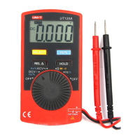
Details the multimeter's LCD display, SELECT button, and Relative Value Measurement (REL) button.
Describes the function selection knob, Hz/% measurement, Data Hold button, and input terminals.
Used to switch between resistance, capacitance, buzzer continuity, and diode measurements.
Sets a reference value for subsequent measurements, subtracting it from new readings.
Locks displayed values on the LCD, allowing for later review without losing the reading.
Switches between Hz and % measurement modes for DCV, ACV, and frequency functions.
Steps for measuring DC voltage, including setting the knob, connecting probes, and reading the LCD.
Procedure for measuring AC voltage, covering knob setting, probe connection, and reading display.
Guide to measuring resistance, including setting the knob, connecting test pens, and reading results.
Instructions for measuring frequency and duty cycle, including setting the knob and connecting test pens.
Procedure for testing diodes and continuity, including setting the knob and connecting test pens.
Steps for measuring capacitance, including setting the knob, using relative mode, and connecting test pens.
Details general parameters like voltage limits, range selection, display max, operating temperature, and dimensions.
Provides accuracy data for DC Voltage, AC Voltage, Resistance, Capacitance, Frequency, Duty Cycle, Diode, and Continuity.
| Display | LCD |
|---|---|
| Diode Test | Yes |
| Continuity Buzzer/Test | Yes |
| Data Hold | Yes |
| Auto Power Off | Yes |
| Auto Range | Yes |
| Input Impedance for DC Voltage Measurement | 10MΩ |
| Operating Temperature | 0°C to 40°C |
| Safety Rating | CAT III 600V |
| Display Count | 4000 |
| DC Current | 40mA |
| Resistance | 400Ω/4kΩ/40kΩ/400kΩ/4MΩ/40MΩ ±(0.8%+3) |
| Capacitance | 40nF/400nF/4µF/40µF/100µF ±(3.0%+5) |
| Frequency | 10Hz-10MHz |