P/N:110401104251X
8.Temperature measurement ( ) (See
Figure 10)
To set knob.
To place function knob to
Figure 10
To select functions.
To connect load.
1) LCD will display OL if failing to insert
temperature sensor. Clamp meter will display
current indoor temperature after user inserting
temperature sensor.
2) The protection for the temperature range is
1KΩ resistor(R59). any conductor with voltage
present cannot be inserted into input jack to
avoid.
A
9. DC current measurement ( ) (See
Figure 11)
To set knob.
To place function knob to 40A or 600A
To select functions.
The meter defaults at DC Current Mode.
To connect load.
Figure 11
Please do not loosen trigger suddenly. As a
sensitive device, Hall element will be sensitive to
heat and mechanical stress to different extents
in addition to magnetic sensitivity. Collision will
cause short-term reading variation. Please open
the clamp head by pressing trigger then fetch
measured conductor by clamp head and loosen
trigger slowly until it is closed completely. Please
check if measured conductor is in the middle of
clamp head or not. Additional error may be caused
if failing to place it in the middle of clamp head.
Clamp meter can measure a current conductor
once and measurement reading error may be
caused if measuring two or more current
conductors at the same time.
10. AC current measurement ( ) (See
Figure 12)
To set knob.
To place function knob to 40A
or 600A
To select functions.
To press SELECT key for AC current
measurement;
To connect load.
Figure 12
Please do not loosen trigger suddenly. As a
sensitive device, Hall element will be sensitive to
heat and mechanical stress to different extents
except magnetic sensitivity. Collision will cause
short-term reading variation.Please open the
clamp head by pressing trigger then fetch meas
-ured conductor by clamp head and loosen trigger
slowly until it is closed completely. Please check
if measured conductor is in the middle of clamp
head or not. Additional error may be caused if
failing to place it in the
middle of clamp head.
Clamp meter can measure
a current conductor
IX. Technical Indicators
1.General specification
LCD display: 4000 counts;
Polarity display: Automatic display;
Overload display: To display OL or -OL ,
Low Battery Indication: shows as battery
voltage is less than required working voltage.
Sampling rate: 3 times/second;
Sensor category: Hall affect sensor for DC/AC
measurement;
Error of testing position: 1.0% of additional
reading error may be caused if failing to place
measured source to center of clamp head during
current measurement;
Shock-resistant: pass 1m drop test;
Max.clamp Opening : 28mm diameter;
Max. Tested Conductor: 26mm diameter;
Influence of electromagnetic field: Device used
near electromagnetic field may display unstable
or incorrect reading;
2.Environment limitation
Indoor use
The
altitude height: 2,000m
Safety rules: ICE 1010-1 CAT.II 600V
CAT.III300V
Pollution degree: 2
Operation temperature & humidity: 0 to 30
(not more than 80%R.H.)
30 to 40 (not more than 75%R.H.)
40 to 50 (not more than 45%R.H.)
Storage temperature & humidity: -20 to +60
(not more than 80%R.H.)
3.Electrical specification
Accuracy:
Calibration period for 1 year
Ambient temperature: 23 5
Ambient humidity: Not more than 80% R.H.
Temperature coefficient:0.1*precision/1
(1)DC voltage ( )
Range
400.0mV
4.000V
40.00V
400.0V
600V
Resolution
0.1mV
1mV
10mV
100mV
1V
Accuracy
(0.8%+3)
(0.8%+1)
(1%+3)
Overload protection
600V DC/AC
Input impedance: 10M Ω
(2)AC voltage ( )
Range
Resolution
Accuracy
Overload protection
4.000V
40.00V
400.0V
600V
1mV
10mV
100mV
1V
(1%+5)
(1.2%+5)
600V DC/AC
Input impedance: 10M //not less than 100pF
Frequency response: 40Hz~400Hz
AC conversion type:
AVG response, RMS value for sinewave input.
(3) Resistance ( )
Range
400.0
4.000K
40.00K
400.0K
4.000M
40.00M
Resolution
100m
1
10
100
1K
10K
Accuracy
(1.2%+2)
(1%+2)
(1.2%+2)
(1.5%+2)
Overload protection
600Vp
(4) Diode test ( )
Range
Resolution
Accuracy
Overload protection
1mV
To display
positive pressure
drop. (Open circuit
voltage is about
600Vp
(5) Continuity test ( )
Range
Resolution
Accuracy
Overload protection
600Vp
Buzzer will ring if
equal to
10 .
(Open circuit
voltage is about
0.1
Note: Buzzer will ring or not ring if measured
resistance exceeds 10
approximate
1.48V.)
it is less than or
0.45V.)
(6) Capacitance ( )
Range
Resolution
Accuracy
Overload protection
600Vp
4nF
40nF
400nF
4µF
40µF
µF
0.001nF
0.01nF
0.1nF
0.001µF
0.01µF
0.1µF
(4.0%+3)
(5.0%+10)
To measure under RELATIVE measurement mode;
(7) Frequency (Hz)
Range
10Hz
100Hz
1kHz
10kHz
100kHz
1MHz
10MHz
Resolution
0.001Hz
0.01Hz
0.1Hz
1Hz
10Hz
100Hz
1kHz
(Reading is only for reference.)
Accuracy
Overload protection
(0.5%+3)
600Vp
Sensitivity: 300mV rms if 100kHz;
600mV rms if 100kHz;
800mV rms if 1MHz;
(8) Temperature ( )
Range
-40 ~
1,000
Accuracy
Overload protection
-40 ~0
0 ~400
400 ~1,000
(8%+5)
(2.5%+3)
(3.0%+3)
Plug-in resistance
of 1K
Note:
1) There is no voltage protection for temperature
ranges. It is not allowed to insert electrified
conductor into jack to avoid burnout of 1K
resistance;
100
2) K type thermocouple (Ni-Cr~Ni-Si) is only
suitable to temperature measurement of less
than 230 . Rod type temperature sensor shall
be used for temperature measurement of more
than 230
.
(9) DC current ( )
Range
40.00A
600A
0.01A
1A
Accuracy
(2%+5)
Overload protection
600A DC/AC
Note:
Current measurement function must be operated
between
0 and 40 . Current direction is
from bottom to top for positive reading during
DC current measurement. (As shown in Figure
11, panel is on the top and bottom cover is on the
bottom.) Please do not loosen the trigger
suddenly after pressing. As a sensitive device,
Hall element will be sensitive to heat and
mechanical stress to different extents addition to
magnetic sensitivity. Collision will cause short
-term reading variation.
More correct
by following operation methods:
Press the trigger and open clamp head to
fetch measured conductor by clamp head then
loosen trigger slowly until clamp head is closed
completely. Please check if measured conductor
is in the middle of clamp head or not. Additional
reading error of 1.0% may be caused if failing
to place it in the middle of clamp head;
To remove clamp head away from the current
conductor;
To press REL key for display resetting;
To repeat step
;
To gain more correct reading by above
measurement steps;
Resolution
measurement can be guaranteed
(10) AC current ( )
Range
40.00A
600A
0.01A
1A
Accuracy
Overload
protection
600A DC/AC
Resolution
(2.5%+8)
(2.5%+5)
Frequency
response
50Hz~60Hz
Note:
Current measurement function must be fulfilled
between 0 and 40 . Frequency response:
50Hz~60Hz;
Instable or incorrect inductive reading with less
than 10 words may be displayed in AC current
gear and it will not influence measurement result.
Please do not loosen trigger suddenly. As a
sensitive device, Hall element will be sensitive to
heat and mechanical stress to different extents
in addition to magnetic sensitivity. Collision will
cause short-term reading variation.
AC conversion type:
AVG response; RMS value for sinewave input.
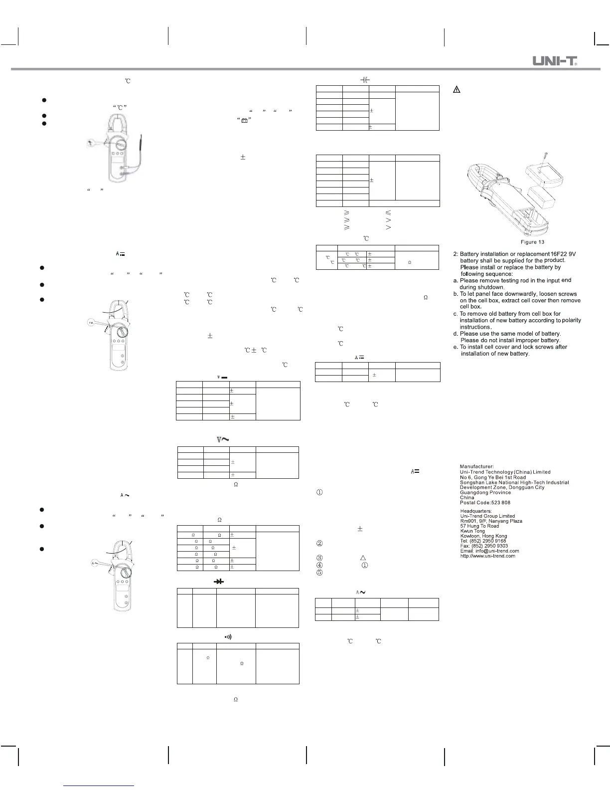
X. Maintenance(See Figure 13)
Warning: Please remove testing rod before
opening bottom cover to avoid electric shock.
1. General maintenance
A. The clamp meter must be repaired and served
by qualified professional repair personnel or
designated repair department.
B. To clean the shell periodically by dry cloth.
However, it is not allowed to use detergent
with abrasive or solvent .
once and measurement reading error may be
caused if measuring two or more current cond
-uctors at the same time.
(a% readings + b digits)

 Loading...