Do you have a question about the UNI-T UT208 and is the answer not in the manual?
Read Safety Information and Rules for Safe Operation carefully before using the Meter to avoid electric shock or personal injury.
Describes the meter as a 3 5/6 digits, steady operation, reliable measuring instrument with overload protection.
Local level, appliance, PORTABLE EQUIPMENT etc., with smaller transient overvoltages than CAT. III.
Distribution level, fixed installation, with smaller transient overvoltages than CAT. IV.
Identifies conditions and actions that pose hazards to the user or may damage the Meter or equipment.
Identifies information that the user should pay attention to.
Symbols used on the Meter and in the Operating Manual are explained on page 10.
Adhere to the following rules to avoid electric shock, personal injury, or damage to the Meter or equipment.
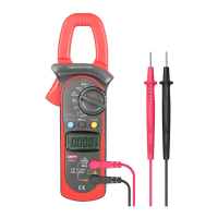
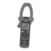
Protects the user's hand from touching dangerous areas.
Press lever to open transformer jaws; releasing pressure closes them.
Points for connecting test leads.
The screen where measurements are shown.
Selects measurement modes and ranges.
Designed to pick up AC/DC current by transferring it to voltage.
Identifies the functional buttons on the meter.
Details operations for SELECT, MAX/MIN, and HOLD buttons.
Describes HOLD button operations: entering/exiting mode, backlight control.
Measures frequency and duty cycle when Meter is at %Hz, V~, and A~.
Zeros the display before measuring DC current.
Indicator for Surge current.
Minimum and Maximum reading displayed.
Indicator for zeroing.
Data hold is active.
Meter is in auto range mode.
True RMS indicator.
Indicators for AC voltage/current and DC voltage.
The battery is low. Warning: Replace battery to avoid false readings and injury.
Sleep mode is on.
Indicates test of diode.
The continuity buzzer is on.
Ω, ΚΩ, ΜΩ: Units for resistance measurement.
Hz, kHz, MHz: Units for frequency measurement.
mV, V: Units for voltage measurement.
A: Unit for current measurement.
Units for temperature measurement: Centigrade and Fahrenheit.
Duty cycle measurement.
Instructions for measuring DC and AC voltage using the meter.
Do not measure voltages higher than 600V AC/DC to avoid shock or damage.
Lists the available DC voltage measurement ranges: 6.6V, 66V, and 600V.
Lists the available AC voltage measurement ranges: 6.6V, 66V, and 600V.
Steps to connect the meter for DC/AC voltage measurements, including lead insertion and switch setting.
Disconnect testing leads after completing DC/AC voltage measurement.
Disconnect power and discharge capacitors before measuring resistance to avoid damage.
Lists the available resistance ranges from 660Ω to 66MΩ.
Steps to connect the meter for resistance measurement, including lead insertion and switch setting.
Disconnect power and discharge capacitors before testing diodes to avoid damage.
Uses diode test to check semiconductors by measuring junction voltage drop.
Steps to connect the meter for testing diodes out of a circuit.
Disconnect power and discharge capacitors before continuity testing to avoid damage.
Steps to connect the meter and test for continuity, noting buzzer behavior based on resistance.
Do not measure voltages higher than 600V AC/DC to avoid shock or damage.
Lists the available frequency measurement ranges from 660Hz to 66MHz.
Steps to connect the meter for frequency measurement, including lead insertion and switch setting.
Do not measure voltages higher than 600V AC/DC to avoid shock or damage.
The duty cycle measurement range is 0.1%~99.9%.
Steps to connect the meter for duty cycle measurement, including lead insertion and switch setting.
Measurement ranges for DC current are 66A and 1000A.
Steps to measure DC current using the transformer jaw.
Measurement ranges for AC current are 66.00A and 1000A.
Steps to measure AC current using the transformer jaw.
Procedure to measure surge current, including setting the rotary switch and pressing SELECT.
Disconnect conductor from jaw after AC current measurement.
Range for temperature measurement is -40°C to 1000°C and -40°F to 1832°F.
Steps to connect the meter and temperature probe for measuring temperature.
Meter automatically turns off after 15 minutes of inactivity to preserve battery.
Meter can be activated by turning rotary switch or pressing buttons; Sleep Mode can be disabled.
Details display, polarity, overloading, sampling, deviation, drop test, jaw size, power source.
Provides information on battery life, meter dimensions, and weight.
Specifies suitability for indoor use, operating/storage altitude, and temperature/humidity limits.
Defines accuracy as ± (a% reading + b digits) with 1-year guarantee and temperature coefficient.
Details accuracy, resolution, and overload protection for DC voltage ranges.
Details accuracy, resolution, and overload protection for AC voltage ranges.
Input impedance, frequency response, and adjustments for non-sine wave input.
Details accuracy, resolution, and overload protection for resistance measurements.
Details accuracy, resolution, and overload protection for diode testing.
Details accuracy and overload protection for continuity testing, noting buzzer behavior.
Details accuracy, resolution, overload protection, and input sensitivity for frequency measurement.
Details accuracy and overload protection for duty cycle measurement.
Details accuracy, resolution, and overload protection for DC current measurement.
Operating temperature must be 0°C ~ 40°C when measuring current.
Notes on reading stability, sensitivity to shock, and precise measurement procedure.
Details accuracy, resolution, frequency response, and overload protection for AC current.
Details accuracy, resolution, and overload protection for temperature measurement.
Do not attempt to repair or service unless qualified; avoid getting water inside the case.
Instructions for cleaning the meter, terminals, and storage precautions.
Replace battery when indicator appears to avoid false readings and injury.
Steps to turn off, disconnect, open case, replace battery, and reassemble.
Detailed steps for replacing the battery: turn off, disconnect, open, replace, reassemble.
| Display | LCD |
|---|---|
| Digits | 3.5 |
| Max Voltage Measurement | 600V |
| Diode Test | Yes |
| Continuity Test | Yes |
| Type | Clamp Meter |
| Frequency Measurement | 10Hz~10MHz |
| AC Voltage Range | 0.1V~600V |
| DC Voltage Range | 0.1V~600V |
| Frequency Range | 10Hz~10MHz |
| Weight | 300g |