EasyManua.ls Logo

UNI-T UT60C

UNI-T UT60C
38 pages
To Next Page IconTo Next Page
Loading...
3
4
4
5
6
7
8
9
11
12
12
14
15
16
17
18
19
20
21
22
22
24
24
25
25
25
25
26
27
27
27
28
Unpacking Inspection
Rules For Safe Operation
Title
Page
Table of Contents
1
Model UT60B/C/E: OPERATING MANUAL
D. Continuity Test
International Electrical Symbols
AC Voltage Measurement
Capacitance Measurement
The Use of Relative Value Mode
The Meter Structure
Turning on the Display Backlight
General Specifications
Resistance
Overview
Safety Information
Rotary Switch
Functional Buttons
Display Symbols
Measurement Ranges
A.
B.
Measurement Operation
A.
B.
C.
D. Testing for Continuity
E.
F.
G.
H.
I. Temperature Measurement
(Model UT60C/UT60E)
J.
Operation of Hold Mode
The POWER Button
The BLUE Button
Sleep Mode (Model UT60B/UT60C)
Accuracy Specifications
A. DC Voltage
B. AC Voltage
C.
Selecting a Measurement Range
Manual Ranging and Autoranging
DC Voltage Measurement
Measuring Resistance
Frequency Measurement
DC or AC Current Measurement
Testing Diodes
Measuring Duty Cycle
Question and Answer IconNeed help?

Do you have a question about the UNI-T UT60C and is the answer not in the manual?

UNI-T UT60C Specifications

General IconGeneral
Data holdYes
Product typeDigital multimeter
Frequency range0.01 - 10000 kHz
AC current range0.4 - 10 A
AC voltage range4 - 750 V
DC voltage range0.4 - 1000 V
Temperature measurement range-40 - 1000 °C
Battery voltage9 V
Dimensions (WxDxH)85 x 177 x 40 mm
Weight and Dimensions IconWeight and Dimensions
Weight340 g

Summary

Overview

Unpacking and Safety Information

Unpacking Inspection

Lists items included in the package for inspection.

Safety Information

Explains safety standards, warnings, and notes for safe operation.

Rules for Safe Operation

Rules For Safe Operation

Provides essential rules to avoid electric shock, injury, or meter damage.

Electrical Symbols and Meter Notes

International Electrical Symbols

Explains common electrical symbols used in the manual and on the meter.

Meter Structure and Components

The Meter Structure

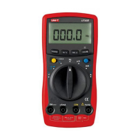
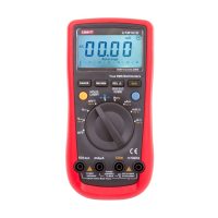
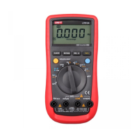
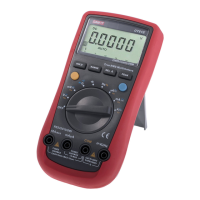
Details the components and input terminals of the multimeter.

Rotary Switch Functionality

Rotary Switch

Explains the functions associated with each position of the rotary switch.

Functional Buttons Overview (1)

Functional Buttons (1)

Describes the operation of the POWER and BLUE buttons for various functions.

Functional Buttons Overview (2)

Functional Buttons (2)

Details the operations of RANGE, Hz/%, REL, and HOLD buttons.

Display Symbols Explained

Display Symbols (1)

Explains common symbols displayed on the LCD screen.

Measurement Range Selection

Selecting a Measurement Range

Guides on choosing the correct range for accurate measurements.

Manual Ranging and Autoranging

Explains the Meter's manual and autorange capabilities.

Autoranging and Manual Ranging

Measurement Ranges (2)

Details how to enter/exit manual range mode and autorange behavior.

DC Voltage Measurement Procedure

DC Voltage Measurement

Step-by-step guide to measuring DC voltage with the meter.

AC Voltage Measurement Procedure

AC Voltage Measurement

Step-by-step guide to measuring AC voltage with the meter.

Resistance Measurement Procedure

Measuring Resistance

Instructions for measuring resistance, including range and precautions.

Continuity and Diode Testing

Testing for Continuity

Guide for performing continuity tests using the meter's buzzer.

Testing Diodes

Instructions for testing diodes and semiconductor junctions.

Capacitance Measurement

Capacitance Measurement

Steps for measuring capacitance, including ranges and precautions.

Frequency Measurement

Frequency Measurement

Instructions for measuring frequency, including range and connections.

Duty Cycle Measurement

Measuring Duty Cycle

Guide to measuring duty cycle percentage of a signal.

Temperature and Current Measurements

Temperature Measurement (Model UT60 CUT60 E)

Procedure for measuring temperature using the meter.

DC or AC Current Measurement

Warnings and setup for measuring DC and AC current.

Current Measurement Details

Current Measurement

Detailed steps for measuring DC and AC current.

Special Measurement Modes

Operation of Hold Mode

How to use the data hold function to freeze readings.

The Use of Relative Value Mode

Guide to using the relative value (REL) mode for measurements.

Buttons and Power Management

Buttons and Power Controls

Explains POWER, BLUE buttons, backlight, and sleep mode functions.

General Specifications

General Specifications

Lists key technical specifications of the multimeter.

Accuracy Specifications (Voltage & Resistance)

Accuracy Specifications (1)

Details accuracy for DC Voltage, AC Voltage, and Resistance measurements.

Accuracy Specifications (Other Functions)

Accuracy Specifications (2)

Provides accuracy for Continuity Test, Diode Test, Capacitance, and Frequency/Duty Cycle.

Accuracy Specifications (Temperature & DC Current)

Accuracy Specifications (3)

Details accuracy for Temperature and DC Current measurements.

Accuracy Specifications (AC Current)

Accuracy Specifications (4)

Lists accuracy for AC Current measurements.

Maintenance and Fuse Testing

General Service

Basic maintenance procedures for the meter's exterior and terminals.

Testing the Fuses

Instructions on how to test the meter's fuses.

Battery Replacement

Replacing the Battery

Step-by-step guide to replacing the battery.

Fuse Replacement

Replacing the Fuses

Detailed procedure for replacing the meter's fuses.

RS232 C Serial Port and Software

RS232 C Serial Port (Model UT60 E)

Information on the RS232C port, cable, and serial port settings.

System Requirements for UT60 E Interface Program

Lists the hardware and software requirements for the interface program.

Related product manuals