EasyManua.ls Logo

UNI-T UT60E

UNI-T UT60E
38 pages
To Next Page IconTo Next Page
Loading...
3
4
4
5
6
7
8
9
11
12
12
14
15
16
17
18
19
20
21
22
22
24
24
25
25
25
25
26
27
27
27
28
Unpacking Inspection
Rules For Safe Operation
Title
Page
Table of Contents
1
Model UT60B/C/E: OPERATING MANUAL
D. Continuity Test
International Electrical Symbols
AC Voltage Measurement
Capacitance Measurement
The Use of Relative Value Mode
The Meter Structure
Turning on the Display Backlight
General Specifications
Resistance
Overview
Safety Information
Rotary Switch
Functional Buttons
Display Symbols
Measurement Ranges
A.
B.
Measurement Operation
A.
B.
C.
D. Testing for Continuity
E.
F.
G.
H.
I. Temperature Measurement
(Model UT60C/UT60E)
J.
Operation of Hold Mode
The POWER Button
The BLUE Button
Sleep Mode (Model UT60B/UT60C)
Accuracy Specifications
A. DC Voltage
B. AC Voltage
C.
Selecting a Measurement Range
Manual Ranging and Autoranging
DC Voltage Measurement
Measuring Resistance
Frequency Measurement
DC or AC Current Measurement
Testing Diodes
Measuring Duty Cycle
Question and Answer IconNeed help?

Do you have a question about the UNI-T UT60E and is the answer not in the manual?

UNI-T UT60E Specifications

General IconGeneral
BrandUNI-T
ModelUT60E
CategoryMultimeter
LanguageEnglish

Summary

Uni-T UT60 BCE Meter Overview and Safety

Meter Features and Safety Guidelines

Highlights meter features like autorange and RS232C, and emphasizes safety precautions.

Unpacking Inspection and Safety Standards

Unpacking Contents and Safety Symbols

Lists items to check after unpacking and explains the meaning of safety symbols and warnings.

Safe Operation Rules for Uni-T Meters

Pre-Use Safety Checks and Procedures

Covers inspecting the meter case, leads, and avoiding hazardous environments.

Measurement Safety and Best Practices

Details safe measurement practices, including using correct terminals and discharging capacitors.

Electrical Symbols and Meter Care

International Electrical Symbol Guide

Defines electrical symbols found on the meter and within the manual.

General Meter Care and Maintenance Tips

Provides advice on cleaning, servicing, indoor use, and battery care.

Uni-T UT60 BCE Meter Structure Identification

Component Layout and Input Terminals

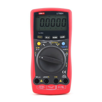
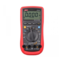
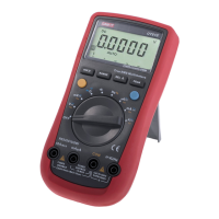
Identifies the LCD display, buttons, rotary switch, and input terminals (HzVΩ, COM, µAmA, 10A).

Uni-T UT60 BCE Rotary Switch Functions

Rotary Switch Positions and Measurement Ranges

Explains each rotary switch position for voltage, resistance, capacitance, frequency, and current measurements.

Uni-T UT60 BCE Functional Buttons (Part 1)

POWER and BLUE Button Operations

Details the functions of the POWER button and the BLUE button for selecting measurement modes.

Uni-T UT60 BCE Functional Buttons (Part 2)

RANGE, Hz%, REL, and HOLD Button Functions

Explains how to use RANGE for manual/auto modes and Hz%, REL, HOLD for advanced functions.

Uni-T UT60 BCE LCD Display Symbols (Part 1)

AC, TRMS, AUTO, RS232 C, and % Indicators

Defines symbols related to AC/DC modes, true RMS, auto ranging, data output, and duty cycle percentage.

Data Hold, REL, Battery, and Warning Symbols

Explains symbols for data hold, relative value mode, low battery, and general warnings.

Display Units and Measurement Range Selection

Understanding Measurement Units (, F, Hz, V, A)

Defines units for resistance, capacitance, frequency, voltage, and current measurements.

Selecting Appropriate Measurement Ranges

Guides on choosing the correct measurement range to prevent overload (OL) and ensure accuracy.

Manual and Auto Ranging Modes

Autorange Mode Explanation

Describes the automatic range selection process for input signals.

Manual Range Mode Operation and Exit

Explains how to activate manual ranging and return to autorange mode.

Measuring DC Voltage with Uni-T UT60 BCE

DC Voltage Measurement Setup and Procedure

Instructions for connecting test leads and setting the rotary switch for DC voltage measurement.

DC Voltage Measurement Notes and Warnings

Details input impedance, potential errors, and safety during DC voltage measurement.

Measuring AC Voltage with Uni-T UT60 BCE

AC Voltage Measurement Setup and Procedure

Instructions for connecting test leads and selecting AC mode for voltage measurement.

AC Voltage Measurement Notes and RMS Value

Covers input impedance, safety disconnection, and true RMS value for Model UT60E.

Measuring Resistance with Uni-T UT60 BCE

Resistance Measurement Setup and Ranges

Details how to measure resistance across various ranges using the Ω setting.

Low Resistance Measurement Accuracy Tips

Advises on compensating for test lead resistance in low-resistance measurements using REL mode.

Testing for Circuit Continuity

Continuity Test Procedure and Buzzer

Explains how to test continuity, identifying a good connection with the buzzer sound.

Testing Diodes and Voltage Drop

Diode Test Procedure and Interpretation

Details the procedure for testing diodes and interpreting forward voltage drop readings.

Capacitance and Frequency Measurement

Measuring Capacitance Values

Instructions for measuring capacitance, including ranges and considerations for lead capacitance.

Measuring Frequency of Signals

Details how to measure frequency from 10Hz to 10MHz using the Hz setting.

Measuring Duty Cycle

Duty Cycle Measurement Procedure

Explains how to measure duty cycle (0.1%-99.9%) by selecting the % symbol on the display.

Temperature and Current Measurement Procedures

Temperature Measurement (UT60 CUT60 E)

Instructions for using the meter to measure temperature in Celsius.

Current Measurement Safety Warnings

Critical safety warnings for in-circuit current measurements, including fuse protection.

DC and AC Current Measurement

Current Measurement Setup and Mode Selection

Covers connecting leads for current measurement and switching between DC and AC modes.

Current Measurement Safety and RMS Value

Provides safety guidelines for high current and explains RMS value differences.

Hold and Relative Value Modes

Using the Hold Mode

Explains how to freeze readings and the limitations of the Hold mode.

Using the Relative Value (REL) Mode

Details how to use REL mode to subtract a stored value from current measurements.

Buttons, Display Backlight, and Sleep Mode

POWER and BLUE Button Functions

Describes the primary functions of the POWER and BLUE buttons.

Display Backlight and Sleep Mode Management

Instructions for activating the display backlight and managing the automatic sleep mode.

General Specifications of Uni-T UT60 BCE

Electrical and Environmental Specifications

Lists voltage limits, fuse types, display, measurement speed, and operating environment.

Physical Dimensions and Safety Compliance

Details dimensions, weight, safety standards (IEC61010), and certifications.

Accuracy Specifications: Voltage and Resistance

DC Voltage Accuracy and Overload Protection

Provides accuracy, resolution, and overload protection for DC voltage measurements.

AC Voltage Accuracy and Frequency Response

Details accuracy, overload protection, and frequency response for AC voltage measurements.

Resistance Accuracy and REL Mode Usage

Specifies accuracy, overload protection for resistance, and notes on using REL mode.

Accuracy Specifications: Continuity, Diode, Capacitance, Frequency

Continuity, Diode, and Capacitance Accuracy

Lists accuracy and overload protection for continuity, diode, and capacitance measurements.

Frequency and Duty Cycle Accuracy

Provides accuracy and overload protection for frequency and duty cycle measurements.

Accuracy Specifications: Temperature and DC Current

Temperature Measurement Accuracy (UT60 CUT60 E)

Details accuracy, resolution, and overload protection for temperature measurements.

DC Current Measurement Accuracy and Duration

Specifies accuracy, overload protection, and measurement duration limits for DC current.

Accuracy Specifications: AC Current

AC Current Measurement Accuracy and Duration

Provides accuracy, overload protection, and measurement duration limits for AC current.

Meter Maintenance and Fuse Testing

General Meter Care and Cleaning

Guidance on cleaning the meter, terminals, and safe storage practices.

Testing Meter Fuses for Continuity

Procedure to test fuses using continuity mode and interpreting the results.

Battery Replacement Guide

Procedure for Replacing the 9 V Battery

Step-by-step instructions for safely replacing the meter's 9V battery.

Fuse Replacement Guide

Procedure for Replacing Meter Fuses

Detailed steps for replacing fuses, specifying fuse types and ratings.

RS232 C Serial Port Configuration (Model UT60 E)

RS232 C Port Cable Pinout and Settings

Details the pinout for the RS232C cable and default serial port communication settings.

System Requirements for Interface Software

Specifies hardware and software requirements for installing the UT60E interface program.

Related product manuals