Do you have a question about the UNI-T UT620C and is the answer not in the manual?
Details of the meter's parts including ports, display, buttons, and test leads.
How to power the meter on/off and monitor battery voltage for optimal performance.
Guide to performing accurate resistance measurements and resolving 'OL' indications.
Control backlight and store measurement data using hold and memory functions.
Steps to view, delete stored data, and upload measurements to a computer.
Procedure for calibrating line resistance to ensure accurate measurements.
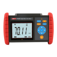
The UNI-T UT620C is a Digital Micro Ohm Meter designed for precise resistance measurements. It is also known as a Micro Ohm Meter, Ohm Meter, or DC Resistance Tester. This device utilizes micro-processor technology and a 4-wire testing method to ensure safe, accurate, and reliable measurements.
The primary function of the UT620C is to measure various types of low resistance. It is mainly applied to:
The product package includes the meter itself, monitoring software, test leads, and a communication cable, providing a comprehensive solution for resistance testing.
The UT620C is designed with user convenience and safety in mind, featuring a large LCD for easy data viewing and intuitive controls.
To power on or off the meter, simply press the power button. Upon powering on, "APO" will appear on the bottom right corner of the LCD, indicating that the auto power-off function is active. The meter will automatically power off after 15 minutes of inactivity to conserve battery life.
The device features a battery voltage check. If a low battery symbol appears on the LCD for 2 to 4 seconds after turning on, it indicates that the battery voltage is low and needs charging. Sufficient battery voltage is crucial for accurate measurements. The battery indication bars on the display will decrease as the battery voltage drops. The meter is powered by a 3.7V 2000mAh lithium battery. Charging typically takes 5-8 hours. It's important to use the original charger provided, as the product does not support fast charging. The charging indicator light will be red during charging and turn green when fully charged.
Before performing any resistance tests, it is essential to clear any insulation or oxidation layers from the surface of the object to be measured. The UT620C is not designed for live testing of resistance or DC low resistance; attempting to do so may damage the meter. For accurate contact, ensure that test clips are clean and free of oxide or foreign objects, especially if they have been used for a long time. A reliable connection between the test leads, the tester, and the measured object is critical. Component heat during testing can introduce errors, so it is recommended to perform tests for 30 seconds with a 30-second interval between measurements. If "OL" (Overload) appears during a test, it means the resistance between the measured points exceeds the range. In such cases, restart the meter and retest. If the "OL" fault persists due to overload protection, it might indicate that the measured resistor is energized, in which case it must be de-energized immediately before retesting. Alternatively, poor contact of the test leads or an open circuit between measured points could also cause an "OL" reading.
In power-on state, the backlight can be turned on or off by pressing the backlight button. This feature is particularly useful in dark environments. By default, the backlight is off when the meter is powered on.
After a measurement is completed, the current displayed data can be held by pressing the "HOLD" button. To store the data, press the "MEM" button. The meter will automatically number and store the current displayed data. If the storage capacity is full, "FULL" will appear on the LCD. The device can store up to 500 groups of data.
After powering on or completing a measurement, the meter can switch to data viewing mode by pressing the "MODE" button. In this mode, "MR" will appear on the LCD. Users can navigate through stored data groups using the arrow buttons (left/right) to set the step as 1 group or 10 groups. To exit data viewing mode and return to testing mode, press the "MODE" button twice. If no data is stored, "NULL" will appear on the LCD. To delete data, press "MODE" to switch to data deletion mode. Use the arrow buttons to select "NO" or "YES". Pressing "NO" followed by the right arrow button will return the meter to the testing state without deleting data. Pressing "YES" followed by the right arrow button will delete all stored data. After deletion, the display will show "DEL".
The UT620C can be connected to a computer via a USB cable. Once connected and the meter is turned on, the monitoring software on the computer can be used to view, upload, and save stored data. The software offers multiple functions, including data viewing, data accessing, data storage, and report generation.
To calibrate line resistance and clear residual resistance, first short-circuit both test clips. Wait for the displayed value to stabilize, then long-press the "MODE" button for 2 to 3 seconds. This process ensures accurate measurements by accounting for the resistance of the test leads themselves. This calibration should only be performed once the displayed value is stable.
Regular maintenance is recommended to keep the product and test leads clean. Avoid dropping or impacting the device. Do not place or store the product in environments with high temperature, high humidity, dews, or direct sunlight for extended periods.
If the product is not used for a long time, it is advisable to charge the battery once every one or two months to maintain its health.
Any use, dismantling, or repair of the device should only be performed by authorized professionals. If any danger arises from the product, discontinue use immediately, seal the product, and send it to an authorized service center for maintenance.
Always pay special attention to safety when using the product. Do not measure any live object. Ensure that the resistor or metal object to be measured is de-energized before measurement to prevent damage to the product. Stop using the device immediately if a test lead is broken during use. The symbol "A" affixed to the product and shown in the user manual indicates that the user must operate according to the provided instructions.
| Model | UT620C |
|---|---|
| Category | Measuring Instruments |
| Display | LCD |
| Max Voltage Measurement | 1000V |
| Data Hold Function | Yes |
| Backlight | Yes |
| Communication Interface | USB |
| Frequency Measurement | 10MHz |
| Max. Test Current | 10A |
| Test Methods | Auto and Manual |
| Data Logging | Yes |
| Current Measurement Range | 10A |
| Voltage Measurement Range | 1000V |
| Temperature Measurement Range | -40℃~1000℃ |
| Safety Rating | CAT III 600V |