21
The resistance ranges are: 200.0 , 2.000k , 20.00k ,
200.0k
, 2.000M and 20.00M .
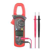
To measure resistance, connect the Meter as follows:
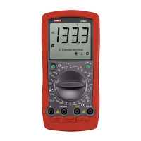
1. Insert the red test lead into the V
terminal and
the black test lead into the COM terminal.
2. Set the rotary switch to an appropriate measurement
position in
range.
3. Connect the test leads across with the object being
measured.
The measured value shows on the display.
Note
l The test leads can add 0.1
to 0.2 of error to the
resistance measurement. To obtain precision readings
in low-resistance, that is the range of 200
, short-
circuit the input terminals beforehand and record the
reading obtained (called this reading as X). (X) is
the additional resistance from the test lead.
Then use the equation:
measured resistance value (Y) – (X) = precision
readings of resistance.
l When the resistance reading
0.5 in the short-circuit
condition, please check for loose test leads or other
reasons.
l For high resistance (>1M
), it is normal taking
several seconds to obtain a stable reading, and it is
better to choose shorter test lead.
l When there is no input, for example in open circuit
condition, the Meter displays “1”.
l When resistance measurement has been completed,
disconnect the connection between the testing leads
and the circuit under test.
Measurement Operation(8)
Model UT90A: OPERATING MANUAL