22
F.Testing Diodes & Continuity
Warning
To avoid possible damage to the Meter and to the
device under test, disconnect circuit power and
discharge all high-voltage capacitors before testing
diodes and continuity.
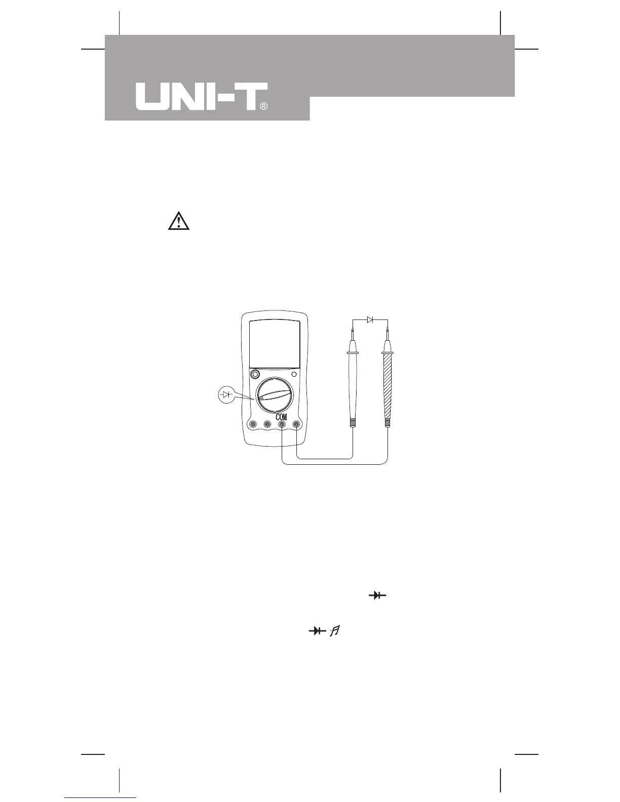
Testing Diodes (see figure 6)
Use the diode test to check diodes, transistors, and other
semiconductor devices. The diode test sends a current
through the semiconductor junction, then measures the
voltage drop across the junction. A good silicon junction
drops between 0.5V and 0.8V.
To test a diode out of a circuit, connect the Meter as follows:
1. Insert the red test lead into the VΩ terminal and
the black test lead into the COM terminal.
2. Set the rotary switch to .
3. For forward voltage drop readings on any semiconductor
component, place the red test lead on the component’s
anode and place the black test lead on the component’s
cathode.
The measured value shows on the display.
Measurement Operation(9)
( figure 6)
red black
Model UT90A: OPERATING MANUAL