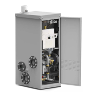
20
Instructions for the installer
For the electrical connection of the
additional safety devices make reference
to the paragraph 3.17 - Connection of the
additional safety devices.
4
3
2
6
5
9
7
6 7
1
8
CERTIFICATION OF THE SUPPLEMENTAL SAFETY DEVICES:
Several notified bodies prescribe supplemental safety
devices.
For the safety valves and on-off gas valves it is necessary to
obtain the ISPESL (Institution for preventive measures and
safety at work) calibration certificate which confirms that they
are free from lead or bossing.
The expansion vessels with a capacity superior to 24 litres
must have be supplied with an approval booklet released by
ISPESL and a manufacturers conformity declaration.
All the accessories must have an ISPESL approval certificate.
SAFETY DEVICES
1. On-off gas valve: a device which has the function of cutting
off the gas supply when the water temperature reaches the
max. predetermined value. The sensible element has to be
installed as nearest as possible to the generator (flow pipe)
at a distance which has to be < 500 mm and must not be able
to be cut-off.
2. Pressure relief valve: it has the function of discharging
in the atmosphere the fluid contained in the generator when
this has, for whatever motive, reached the maximum working
pressure.
PROTECTIVE DEVICES
3. Overheat thermostat: it has the function of shutting down
the generator if the safety thermostat fitted in the boiler
malfunctions. It must be calibrated to a value of < 100°C,
which MUST not be changed.
4. Safety pressure switch: it has the function of shutting
down the generator if it reaches the maximum working
pressure. It must be able to be reset manually.
3.9 - SUPPLEMENTAL SAFETY, PROTECTIVE AND CONTROL DEVICES PRESCRIBED BY
THE GOVERNMENT DECREE 01-12-1975 AND RELATIVE APPLICABLE TECHNICAL
SPECIFICATIONS (CONTAINED IN THE “RACCOLTA R EDITION 1982”)
CONTROL DEVICES
5. Pressure indicator with shock absorber tube and
pressure gauge holder valve: it indicates the effective
pressure existing in the generator. It must be graduated in
“bar” and must have the maximum operating pressure in
scale and be equipped with a 3-way valve with the connection
for the manometer.
6. Thermometer: it indicates the effective water temperature
contained in the generator. It must be graduated in degrees
Celsius with a temperature scale not exceeding 120°C.
7. Bulb holder for a master temperature gauge: it must
be fitted vertically and must have an inside dia. of 10 mm,
in order to locate a mercury master thermometer.
8. Calibrated expansion vessel: it permits the absorption
of the increase in volume of the system’s water following an
increase in temperature and its nominal maximum working
pressure must be higher than the pressure relief valve’s
setting.

 Loading...