20
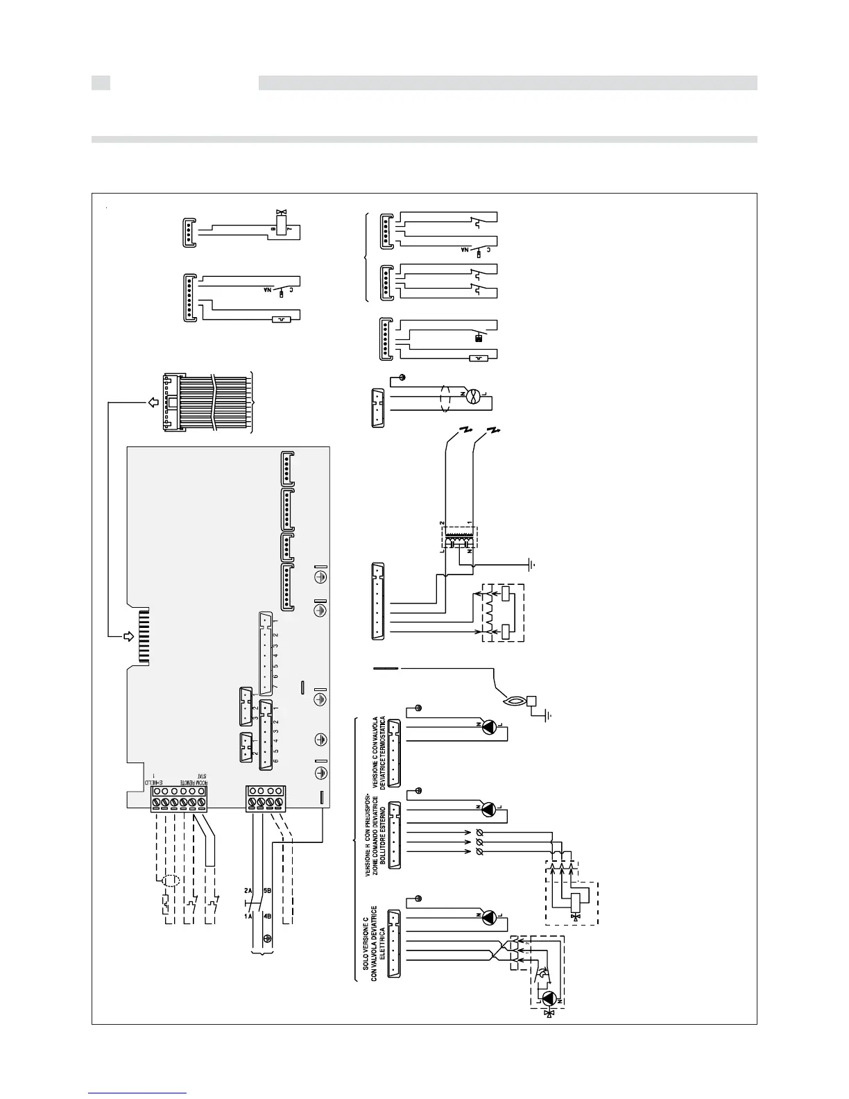
Installation info
KEY
A1...A8 = Connectors
ROD = Connector of the ionisation on
the ignition PCB
Y1 = Connector TA - Outer sensor
Y2 = Connector for supply 230 V-50
Hz
DK = Pressure switch against lack of
water
E. RIV. = Ionisation probe
E. ACC.1= Ignition electrode 1
E. ACC.2= Ignition electrode 2
FL = DHW flow switch
MD = Modulating coil
MVD = Three way valve actuator
(only for E version)
P = Circulating pump
PV = Fan pressure switch
(only for TFS version)
SE = Outer sensor (option)
SR = Heating temperature sensor
SS = D.H.W. temperature sensor
TA 1 = Modulanting digital programmer
(option)
TA 2 = Room thermostat (option)
TF =
Smoke antispillage thermostat
TL = Safety thermostat
V = Fan (only for TFS version)
VG = Gas valve
fig. 21
DISPLAY PCB
A8
65 43 2 1
65432 1
YEL /GREEN
BLUE
GREEN
WHITE
RED
BROWN
P
DH W
CH
MVD
YEL/GREEN
BLUE
BROWN
PR
3
E. RIV.
WHITE
ROD
A6
V2V1
VG
hone