21
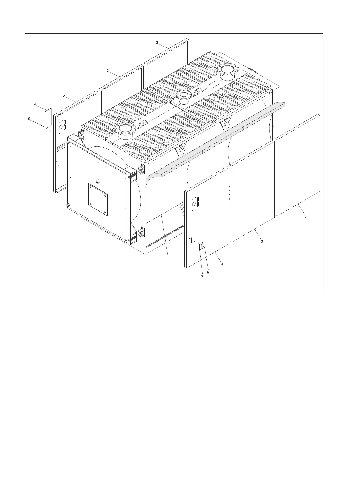
fig. 27
Mounting sequence (Ref. fig. 27)
A) Fit the insulation blanket (1) onto the boiler
shell and secure it in to place using the
elasticated straps (2) provided, ensuring that
the metal clips grip in to the external surface
of the insulation.
Make a covenient cut in the upper part of
the insulation blanket to get easy access
to the bulb holders.
B) For the model ELL 4000, in addition to the
rear panels, pos. 3, (two off per each side)
two side panels are supplied (400 mm
long)(detail non visible), which have to be
fitted on the rear side of the boiler, one for
each side.
Position the L.H. side panels (2 & 3)with
the lower bend inside the bottom L profiles
and hook them to the screws fitted to the
upper square tube.
To determine which one of the front side
panels is the left or the right ensure that
the cable clamp plates (5) are positioned
facing toward the front edge.
C) Position the R.H. side panels (6 & 3) with
the lower bend inside the bottom L profiles
and hook them to the screws fitted to the
upper square tube.
To determine which one of the front side
panels is the left or the right ensure that
the cable clamp plates (5) are positioned
facing toward the front edge.
D) Fit the panel board to the left or right front
side panel.
After removal of the two side screws from
the panel board rotate its cover
towards the front and insert the cables and
the capillaries of thermometer and
thermostats through the slots on its base.
E) Insert the thermometer and thermostat bulbs
in the bulb holders as shown in fig. 28 and
connect the mains, the burner, the pump(s)
and any ancillary equipment to the panel
board.
Close the panel board.
Guide the burner plug through the side cable
clamp plate (5) on the preferred side and
clamp the cable using the cable clamp
supplied.
Fix the side cable clamp plates (5) to the
casing side panels (2 & 6).
F) Remove the protective paper film from data
plate and ventilation requirement label (14) and
fit them at the top front corner of the most
accessible side panel after removal of dust
from the surface.
The data plate and label are in the
documents envelope.
ELLPREX 3000 - 4000
 Loading...