Bulletin 30-020.007
Copyright © 2019 Unico Inc. Page 22
By measuring and totaling the airflow of all outlets, the
total airflow of the system can be closely approximated
and provide a crosscheck for the airflow determined
from the motor amperage using the airflow-amperage
table that is shipped with the Blower module. Use
Table 9 to correct the airflow.
Note: These tables are for the specific motor
installed in each blower module. Be sure the
table used applies to the correct model number
that is shown on the table.
Check Static Pressure Airflow should be verified
using the amps listed on the yellow label on the ST2
blower and from the control board for the EC blower.
If the air flow is low, it is because of a restriction.
Check static pressure to find the restriction and correct.
Measure the external static pressure (see the following
section) in the supply plenum at least two feet (610
mm) from the unit and verify that it is within the
allowable range.
It is not necessary to measure the return duct static
pressure unless it was field fabricated. The maximum
return static pressure (including filters) should be 0.15
inches of water (37 Pa). If it is greater than 0.15 inches
of water column, subtract the extra return system
pressure drop from the supply plenum static pressure
to get the total static pressure drop.
For example: If the supply static pressure is measured
to be 1.6 inches w.c. and the return system pressure
drop is 0.25 inches w.c, the total static pressure drop as
shown on the blower curve is: 1.6 - 0.10 = 1.50. In this
case the static pressure is too high.
If the restrictor plate (standard units only) is not
positioned according to Table 4, the static pressure
reading is not an effective indicator of airflow although
it should still be recorded. In this case, measuring
motor amperage is the only reliable indicator.
Check Outlet Airflow. Measure and record the air
flow from each outlet with a TurboMeter (refer to Tech
Note 113, How to Measure Outlet Airflow, for more
information). Place the TurboMeter against each
outlet, centered as best possible and record the “knots”.
Multiply the knots by 2 to obtain CFM, then sum all
the outlets. The sum is the total airflow; this can be
compared to the outlet indicated by the amperage. A
significant difference could indicate duct leakage.
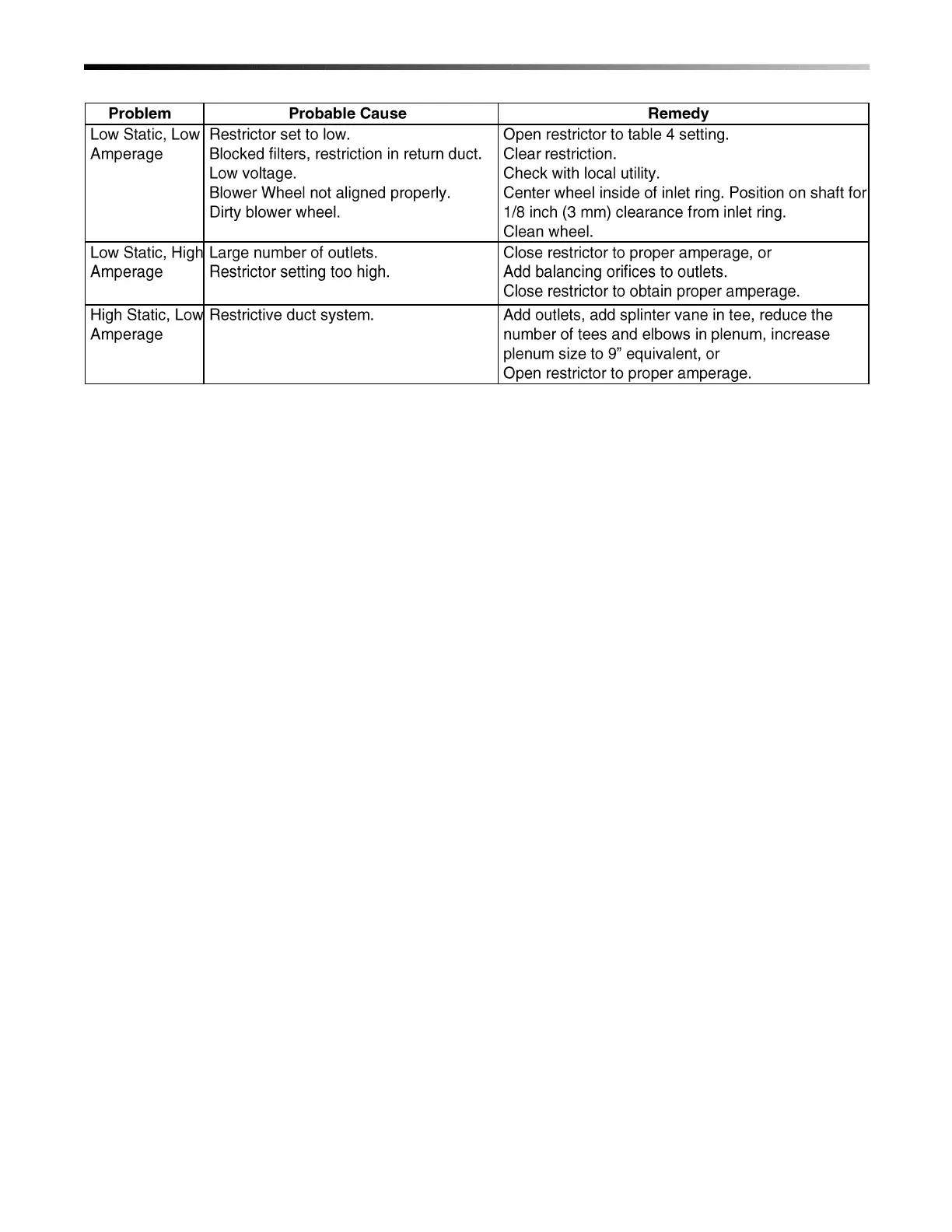
Table 10. Airflow Troubleshooting Chart
How to Measure Static Pressure. Measure the supply
plenum static pressure at least 18-inches (457mm)
from the unit, but before any tee or elbow. A distance
of between 2 and 3-feet (0.6 to 0.9m) is best. Use an
inclined manometer capable of reading at least 2.5
inches of water column (622 Pa), such as Dwyer
Instrument’s model 109 manometer. Be sure to zero the
scale and level the manometer.
A magnehelic gauge that measures up to at least 2.5
inches of water may also be used.
Use a metal tube, typically ¼-inch (6mm) diameter, to
measure the static pressure. Determine where you want
it and cut or punch a small hole in the duct. Make the
hole the same size as the metal tube to prevent leakage.
Insert the metal tube 1-inch (25mm) so that the tip of
the tube is flush to inside wall of the duct and
perpendicular to the air stream as shown in Fig. 32.
Attach the metal tube to the manometer using a rubber
hose (usually supplied with the manometer). Record
the pressure.
Note: If the tube is not perpendicular to the air stream,
the reading will be in error. You will get a higher
reading if the tube is angled toward the air stream.
 Loading...