Bulletin 30-020.007
Copyright © 2019 Unico Inc. Page 21
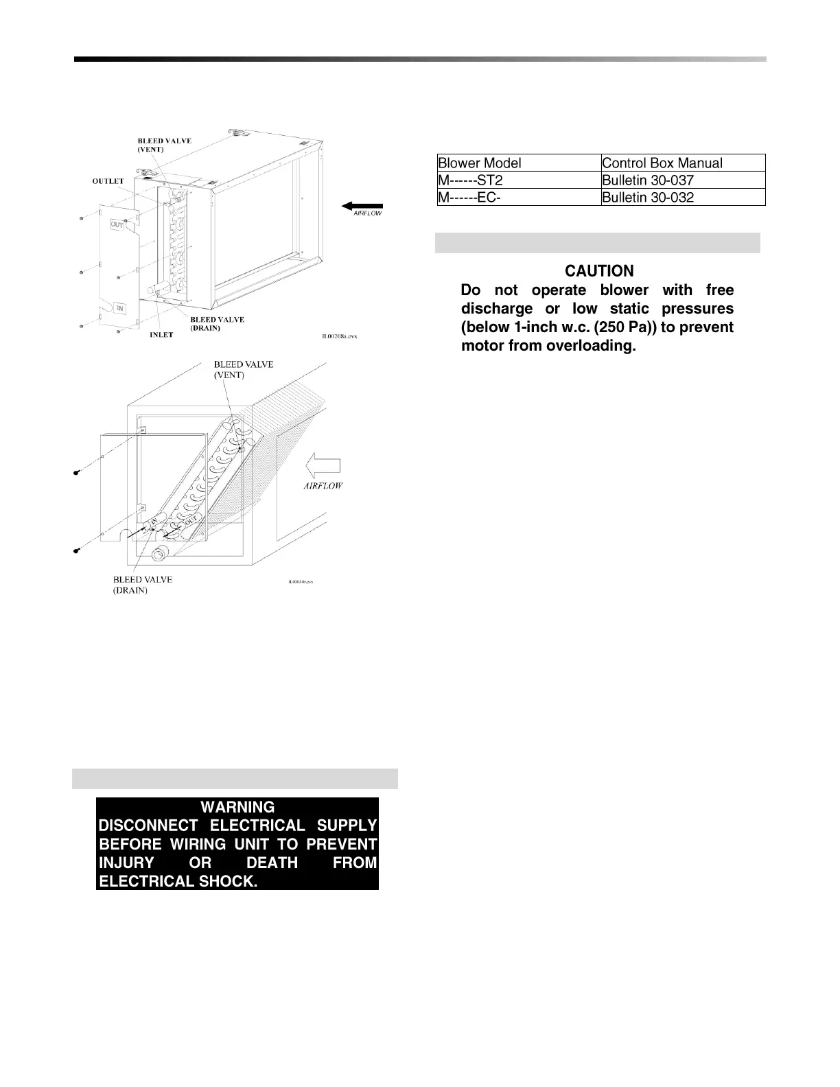
After venting the chilled water coil, replace the access
panel and seal around the connections with the rubber
gasket provided.
Figure 31. Water Coil Connections Coil Cleaning.
The coil should be sprayed with liquid detergent, or
any commercially available evaporator cleaner
solution, thoroughly and rinsed thoroughly before
installation to assure proper drainage of condensate
from the coil. This will eliminate moisture carry-over
and assure maximum coil performance. As an alternate
to cleaning, allow approximately 50 hours of break-in
time to achieve the same results.
WIRING
All electrical wiring must comply with local codes and
ordinances. Blower module controls and components
are bonded for grounding to meet safety standards UL
Standard 1995 and CAN/CSA-C22.2 No. 236 and are
listed by ETL. All 50 Hz units are CE marked and
conform to the Low Voltage 73/23/EEC and EMC
89/336/EEC Directives.
The control wiring, sequence of operation, and
troubleshooting are included in a separate bulletin for
each control box.
Table 9. Control Box Manuals
CHECKING AIR FLOW
After the system is installed and before charging
system, check for proper airflow. Record the position
of the restrictor plate, the plenum static pressure, and
the motor amperage (standard units only). With this
information, the amount of airflow can be determined.
As a recommended further check on airflow, use a
velometer to measure the airflow from each outlet.
The most convenient instrument to use is a hand held
vane type velocity meter that fits directly over the
outlet. The Turbo-Meter (Davis Instruments Catalog
No. DS105I07) or equivalent meter will give a direct
LED readout on the Knots (FPM x 100) setting, when
multiplied by 2 gives the CFM of the outlet within an
accuracy of 10%. (Multiply ‘knots’ by 0.94 to obtain
L/s.) Refer to Technote 113 for more information.
 Loading...