4
/10
The connection to the sensor electrodes is made by the 2-pole connector X3 and a coaxial cable.
According to the drawing (see Figure 1), the core is connected to the left terminal X3/1 (measuring
electrode) and the shield to the right terminal X3/2 (opposite electrode).
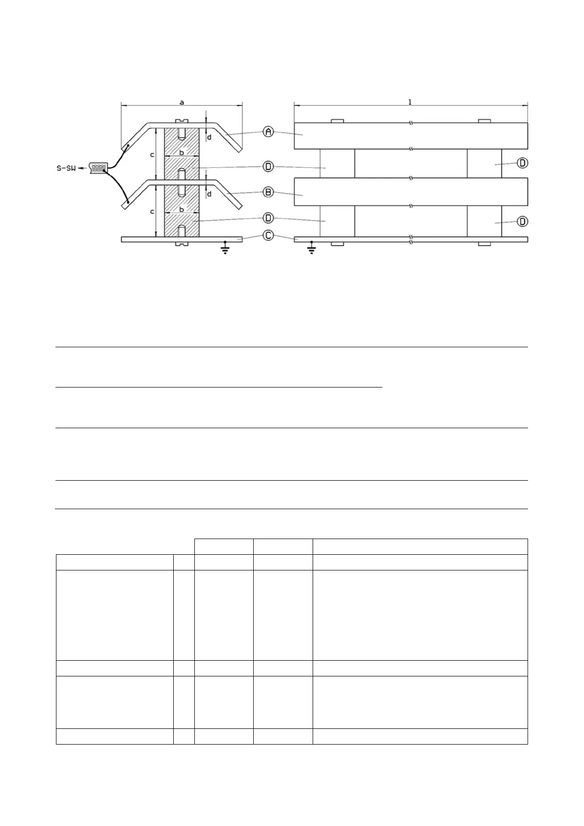
2.2 Sensor Electrodes
Figure 2
The sensor electrodes can have any geometric shape. It is only important that the two elec-
trodes have approximately the same area and are fixed to a grounded structure.
electrode
The measurement electrode is connected
to X3
/1 of the evaluation unit via the core
conductor of the coaxial cable.
material (sheet steel, alu-
minum, etc.). They should
have the same design.
The opp
osite electrode is connected to
X3/
2 of the evaluation unit via the shield of
the coaxial cable.
The design of the mounting structure depends on the conditions at the
installation place. It must be made of conductive material (metal, for fur-
ther examples see above).
The mounting structure must be connected to the earth potential!
The spacers must be made of electrically isolating material (plastic / ce-
ramic, see table below).
Construction Rules
a 10 mm 200 mm
b no specifi-
cation
no specifi-
cation
Electrically isolating material (plastic / ce-
ramic).
The selected diameter must ensure suffi-
cient mechanical stability.
Spacers are available as accessories from
UNICONTROL (UC spacer M4, M6, M10
and M12.
c 5 mm 80 mm
Capacity
d no specifi-
cation
no specifi-
cation
The material mechanical capacity is not crit-
ical. It should be chosen
the electrodes have enough mechanical sta-
bility.
l 20 mm 4000 mm
The sensor electrodes can have any geometric shape. It is important that the two electrodes
have approximately the same areas.
 Loading...