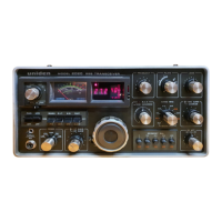
UNIDEN 2020
Sid 2 (26)
3. R.I.T CIRCUIT ALIGNMENT
3-1 Test Equipment Required
(1) None
3-2 Adjustment Procedures
(1) Set the main dial at 50, on any BAND or SEGMENT selection.
(2) Pull out RF ATT knob and make the marker oscillator work to obtain about
1,000 Hz beat.
(3) Set R.I.T knob to 0 at the WIDE (normal) position.
(4) Adjust potentiometer R665 in AVR unit to obtain the same beat at ON or
OFF of the R.I.T SWITCH.
(5) Again try the same adjustment on R664 in AVR at the NARROW (pull)
position of R.I.T.
4. S-METER ADJUSTMENT
4-1 Test Equipment Required
(1) Standard Signal Generator (SSG)
4-2 Adjustment Procedures
(1) Connect SSG output to antenna jack.
(2) Set MODE SWITCH to USB.
(3) Set BAND SWITCH to 14.0, SEGMENT SWITCH at 200/300, and tune the
main dial to recive 14.200 MHz signal.
(4) Turn RF GAIN CONTROL fully clockwise.
(5) Turn RF ATT CONTROLL fully clockwise.
(6) Tune PRESELECT knob to obtain maximum nois output.
(7) Set SSG frequency at other than 14.200 MHz and keep minimum output
level.
(8) Turn potentiometer R387 in the IF unit fully counterclockwise. Then, return
it slowly clockwise and stop just befor S-Meter start moving.
(9) Feed 40 dB of 14.200 MHz unmodulated output to tranciver, and turn the
dial to obtain maximum S-Meter readings.
(10) Adjust potentiometer R389 on the IF unit, so that the S-Meter indicator S-9
readings.
(11) Set SSG Output at 80 dB.
(12) Adjust potentiometer R392 on the IF unit, so that the indicator shows full-
scale readings.
(13) Repeat (9) – (12) adjustment until both prospected readings ar available.

 Loading...