Do you have a question about the UniFi USW-16-POE and is the answer not in the manual?
Describes the touch display states and animations for the UniFi Switch.
Details the LEDs for PoE status on RJ45 ports 1 through 8.
Explains the LEDs indicating speed, link, and activity for RJ45 ports 1 to 16.
Covers the LEDs for speed, link, and activity on SFP ports 17 and 18.
Describes the capabilities of RJ45 ports 1-8, including Ethernet and PoE output.
Details the specifications of RJ45 ports 9-16 for Ethernet connections.
Explains the functionality of the hot-swappable SFP ports supporting 1 Gbps connections.
Outlines the two functions of the reset button: restart and factory reset.
Instructs on connecting the power cord to the device's power port.
Provides the ISED Canada certification number for the device.
States compliance with Class A of CISPR 32 for Australia and New Zealand.
Confirms the product's compliance with all applicable directives via CE marking.
Statement regarding compliance with the Waste Electrical and Electronic Equipment directive.
Indicates that a Declaration of Conformity document is available for the product.
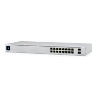
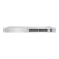
The USW-16-POE is a managed Gigabit Layer 2 switch with sixteen RJ45 Ethernet ports and two SFP ports, designed for network expansion and power over Ethernet (PoE) capabilities. It is suitable for various network environments, from small businesses to larger enterprise deployments, offering robust connectivity and management features.
The primary function of the USW-16-POE is to provide high-speed network connectivity and Power over Ethernet (PoE) to compatible devices. It features sixteen 10/100/1000 Mbps RJ45 Ethernet ports, with the first eight ports supporting 802.3af/at PoE output. This allows the switch to power devices such as IP cameras, VoIP phones, and wireless access points directly through the Ethernet cable, simplifying network infrastructure and reducing the need for separate power adapters. The remaining eight RJ45 ports (9-16) provide 10/100/1000 Mbps Ethernet connections without PoE.
In addition to the RJ45 ports, the USW-16-POE includes two hot-swappable 1 Gbps SFP ports (17-18). These SFP ports enable fiber optic connectivity, extending network reach over longer distances or providing high-bandwidth uplinks to other network devices. This flexibility makes the switch suitable for diverse network topologies, including those requiring fiber backbones.
The switch is managed through the UniFi Controller software, a centralized platform that allows for easy configuration, monitoring, and management of all UniFi devices on a network. This software-defined networking (SDN) approach simplifies network administration, enabling users to provision, manage, and troubleshoot their network from a single interface. The UniFi Controller provides a comprehensive overview of network performance, device status, and client connectivity, facilitating efficient network operations.
The USW-16-POE also incorporates a touchscreen display on the front panel, offering real-time status information and basic device interactions. This display provides visual feedback on bootup animation, adoption status, and location animation, enhancing user convenience during deployment and troubleshooting.
The USW-16-POE is designed for ease of use and flexible deployment. Its rack-mountable form factor allows for integration into standard 19-inch server racks, occupying 1U of height. The package includes rack-mount brackets and screws for secure installation. Alternatively, the switch can be placed on a desktop or shelf for smaller deployments.
The touchscreen display on the front panel provides immediate visual feedback on the switch's operational status. During bootup, it shows an "Initializing" animation. A "Steady White" status indicates that the switch is at factory defaults, waiting for adoption by the UniFi Controller. Once successfully adopted and working properly within a network, the display shows "Steady Blue." A "Location Animation" indicates that the "Locate" function has been activated in the UniFi Controller software, helping administrators quickly identify the physical location of the device on a map.
LED indicators for each port provide additional status information. The RJ45 PoE LEDs (Ports 1-8) indicate PoE status: "Off" means no PoE, while "Amber" signifies 802.3af/at PoE. The RJ45 Speed/Link/Activity LEDs (Ports 1-16) show connection speed and activity: "Off" means no link, "Amber" indicates a 10/100 Mbps link with flashing for activity, and "Green" indicates a 1000 Mbps link with flashing for activity. Similarly, the SFP Speed/Link/Activity LEDs (Ports 17-18) provide link and activity status for fiber connections.
Connecting the switch to the network and power is straightforward. The power cord connects to the power port on the rear panel. Ethernet devices are connected to the RJ45 ports, and SFP modules are inserted into the SFP ports for fiber optic connections. When connecting PoE devices, the touchscreen display can be checked to confirm PoE delivery.
The UniFi Controller software simplifies the adoption process. Once the software is installed and running, the switch appears in the "Devices" list on the dashboard. Administrators can then click "Adopt" to integrate the switch into their UniFi network. Upon successful adoption, the System LED on the UniFi Switch turns blue, confirming its integration.
The switch supports various network configurations and applications. Its PoE capabilities are ideal for powering a range of devices without additional power outlets, making it suitable for surveillance systems, IP telephony, and wireless network deployments. The SFP ports offer flexibility for high-speed uplinks or connecting to fiber backbones, extending the network's reach and capacity.
The USW-16-POE is designed for reliable operation with minimal maintenance. However, it includes features to facilitate troubleshooting and system recovery.
A "Reset Button" is located on the rear panel, serving two functions. A quick press and release will restart the UniFi Switch, which can be useful for resolving minor operational issues. Pressing and holding the Reset button for more than five seconds will restore the switch to its factory default settings. This is a critical feature for reconfiguring the device or troubleshooting persistent problems, allowing a fresh start if configuration errors occur.
The UniFi Controller software plays a significant role in ongoing maintenance and monitoring. It provides a centralized dashboard to view the status of all connected UniFi devices, including the USW-16-POE. Administrators can monitor network performance, port status, and PoE usage, allowing for proactive identification and resolution of potential issues. The software also facilitates firmware updates, ensuring the switch operates with the latest features and security enhancements.
For physical installation, it is recommended to use shielded Category 5 (or above) cabling for outdoor applications, grounded through the AC ground of the power supply. This helps protect the network from harmful outdoor environments and destructive ESD events. While the cabling can be outdoors, the UniFi Switch itself should be housed inside a protective enclosure to ensure its longevity and performance.
The system requirements for the UniFi Controller software include a Linux, Mac OS X, or Microsoft Windows 7/8/10 operating system, Java Runtime Environment 1.6 (1.8 or newer recommended), and a web browser like Google Chrome for optimal functionality. Regular updates to the UniFi Controller software are available at ui.com/download/unifi, ensuring access to the latest features and bug fixes.
It is strongly recommended to use UPS backup and power regulation to prevent equipment damage due to stability issues with local AC power. This precaution helps protect the switch and connected devices from power fluctuations, ensuring continuous operation and extending the lifespan of the equipment. Adequate ventilation is also crucial for the switch's operation; maintaining at least 20 mm of clearance next to the ventilation holes ensures proper airflow and prevents overheating.
The USW-16-POE is a robust and versatile switch, offering comprehensive connectivity, PoE capabilities, and centralized management through the UniFi Controller, making it an excellent choice for expanding and managing modern networks.
| Total Ports | 16 |
|---|---|
| PoE+ Ports | 8 |
| Switching Capacity | 32 Gbps |
| Max. Power Consumption | 150W |
| Rack Mountable | Yes |
| Enclosure Characteristics | Metal |
| PoE | Yes |
| PoE+ IEEE 802.3at | Yes |
| Management Interface | Ethernet In-Band |
| Certifications | CE, FCC, IC |
| Power Method | 100-240VAC, 50/60 Hz Universal Input |
| Power Supply | Internal |
| Supported Voltage Range | 100 to 240VAC |
| Interfaces | 16 x RJ45 Gigabit Ethernet Ports |
| Operating Humidity | 10% to 90% Non-condensing |