Do you have a question about the UniFi US-24 and is the answer not in the manual?
Describes the system status indicator light for the device.
Details the LEDs for RJ45 Ethernet ports indicating link, speed, and activity.
Explains LEDs for SFP+ ports, specific to the US-48 model.
Instructions for mounting the switch in a rack.
The UniFi Switch US-24 and US-48 are network switches designed for robust and scalable network deployments, offering a comprehensive set of features for both small and large-scale environments. These devices serve as central components in a network, facilitating high-speed data transfer and efficient management of connected devices.
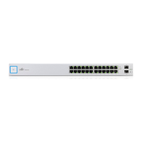
At its core, the UniFi Switch provides a high-performance switching fabric for Ethernet connections. The US-24 model features 24 RJ45 Ethernet ports, while the US-48 model offers 48 RJ45 Ethernet ports, all supporting 10/100/1000 Mbps speeds. This allows for the connection of numerous wired devices such as computers, servers, IP cameras, and other network-enabled equipment. In addition to the standard RJ45 ports, both models include SFP (Small Form-Factor Pluggable) ports for fiber optic connectivity. The US-24 has two 1 Gbps SFP ports, while the US-48 is equipped with two 1 Gbps SFP ports and two 10 Gbps SFP+ ports. These SFP and SFP+ ports enable high-speed uplinks to other network devices, such as core switches or servers, over longer distances than traditional copper Ethernet cables. The SFP+ ports on the US-48 specifically support 10 Gigabit Ethernet connections, providing significant bandwidth for demanding applications.
The UniFi Switch is designed to be managed by the UniFi Network Application, a centralized software platform that allows administrators to configure, monitor, and troubleshoot their entire UniFi network from a single interface. This application provides a graphical user interface for easy management of switch settings, port configurations, VLANs, and other network parameters. The switch also includes a Console Port (RJ45 serial console port) for Command Line Interface (CLI) management, offering an alternative method for advanced configuration and troubleshooting. This is particularly useful for initial setup or when network connectivity is unavailable.
For power, the UniFi Switch connects to an AC power source using the included power cord. Both models also feature a DC Input, allowing for the connection of a redundant or stand-alone DC power source (not included). This redundancy feature is crucial for maintaining network uptime, as the switch can seamlessly switch to the DC power source if the primary AC/DC power supply fails, ensuring continuous operation without interruption. This hot spare capability enhances the reliability of the network infrastructure.
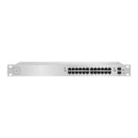
The UniFi Switch is designed for easy installation and integration into existing network environments. It is rack-mountable, fitting into a standard-sized 19-inch wide rack with a minimum of 1U height available. The package includes rack-mount brackets, bracket screws, mounting screws, cage nuts, and rubber feet, providing flexibility for various installation scenarios. For desktop use, the rubber feet can be attached to the bottom of the switch.
The front panel of the switch features LEDs that provide visual feedback on the status of each port and the overall system. The System LED indicates the operational status of the switch, while individual RJ45 Link/Speed/Activity LEDs show the link status, speed (10/100 Mbps or 1 Gbps), and activity for each Ethernet port. Similarly, SFP and SFP+ Link/Speed/Activity LEDs provide status information for the fiber optic ports, indicating link establishment at 1 Gbps or 10 Gbps and flashing to show activity. These LEDs are invaluable for quick diagnostics and monitoring of network traffic.
Connecting power is straightforward: simply plug the included power cord into the power port on the back of the switch. For Ethernet connections, Category 5 (or above) UTP cabling is recommended for indoor applications. For outdoor deployments, shielded Category 5 (or above) cabling is advised, and it should be grounded through the AC ground of the power supply to protect against harmful outdoor environments and destructive ESD events. Ubiquiti recommends using their industrial-grade, shielded Ethernet cable for optimal protection. While cabling can be outdoors, the UniFi Switch itself should always be housed inside a protective enclosure.
The SFP and SFP+ ports allow for flexible fiber optic connectivity. Users can insert compatible SFP or SFP+ modules into these ports and connect fiber optic cables to extend network reach or connect to high-bandwidth devices. The hot-swappable nature of these ports means modules can be added or removed without powering down the switch, minimizing downtime.
The UniFi Switch incorporates several features to ensure reliable operation and ease of maintenance. The Reset Button, located on the front panel, serves two critical functions. A quick press and release will restart the device, which can be useful for resolving minor issues or applying certain configurations. Pressing and holding the Reset button for at least five seconds will restore the device to its factory default settings, a useful feature for troubleshooting or reconfiguring the switch from scratch.
The device is designed for indoor use, and proper ventilation is crucial for its longevity and performance. It is important to maintain at least 20 mm of clearance next to the ventilation holes to ensure adequate airflow and prevent fire hazards. The operating temperature range is specified from -5 to 40° C (23 to 104° F), and operating humidity from 5 to 95% non-condensing, indicating its suitability for typical indoor commercial environments.
The UniFi Network Application provides comprehensive monitoring capabilities, allowing administrators to track port status, traffic statistics, and device health in real-time. This centralized management simplifies the identification and resolution of network issues, reducing the need for direct physical interaction with the switch. Firmware updates, which often include performance improvements and security patches, can also be managed through the UniFi Network Application, ensuring the switch remains up-to-date and secure.
The redundant DC input offers a significant maintenance advantage by providing a failover power source. In the event of a primary power supply failure, the switch automatically switches to the secondary DC power source, preventing network downtime. This allows administrators to address the primary power issue without immediate pressure, as the network continues to operate.
For advanced troubleshooting or specific configurations, the RJ45 serial console port provides direct access to the device's command-line interface. This allows for detailed diagnostics and configuration adjustments that might not be available through the graphical user interface, offering a powerful tool for experienced network administrators. The console port settings, such as baud rate, data bits, parity, stop bits, and flow control, are standard, making it compatible with common serial terminal programs.
The robust construction, featuring an SGCC Steel enclosure, contributes to the device's durability and ability to withstand typical commercial environments. The ESD/EMP protection, rated at Air ± 24 kV and Contact ± 24 kV, helps safeguard the switch from electrostatic discharge and electromagnetic pulses, which can be common in network environments and can cause damage to sensitive electronic components.
Overall, the UniFi Switch US-24 and US-48 are designed to be reliable, manageable, and adaptable network solutions, providing essential switching capabilities with a focus on ease of use, robust performance, and continuous operation.
| Total Non-Blocking Throughput | 26 Gbps |
|---|---|
| Switching Capacity | 52 Gbps |
| Forwarding Rate | 38.69 Mpps |
| Max. Power Consumption | 25W |
| Rackmount | Yes |
| Operating Temperature | -5 to 40° C (23 to 104° F) |
| Operating Humidity | 5 to 95% Noncondensing |
| Management Interface | Ethernet In-Band |
| Certifications | CE, FCC, IC |
| ESD/EMP Protection | Air: ± 24 kV, Contact: ± 24 kV |
| Power over Ethernet | No |
| Ports | 24 x Gigabit RJ45 |
| Power Method | AC Input |
| Power Supply | Internal |
| LEDs Per Port | Speed/Link/Activity |
| Networking Interface | (24) 10/100/1000 Mbps RJ45 Ports (2) 1 Gbps SFP Ports |