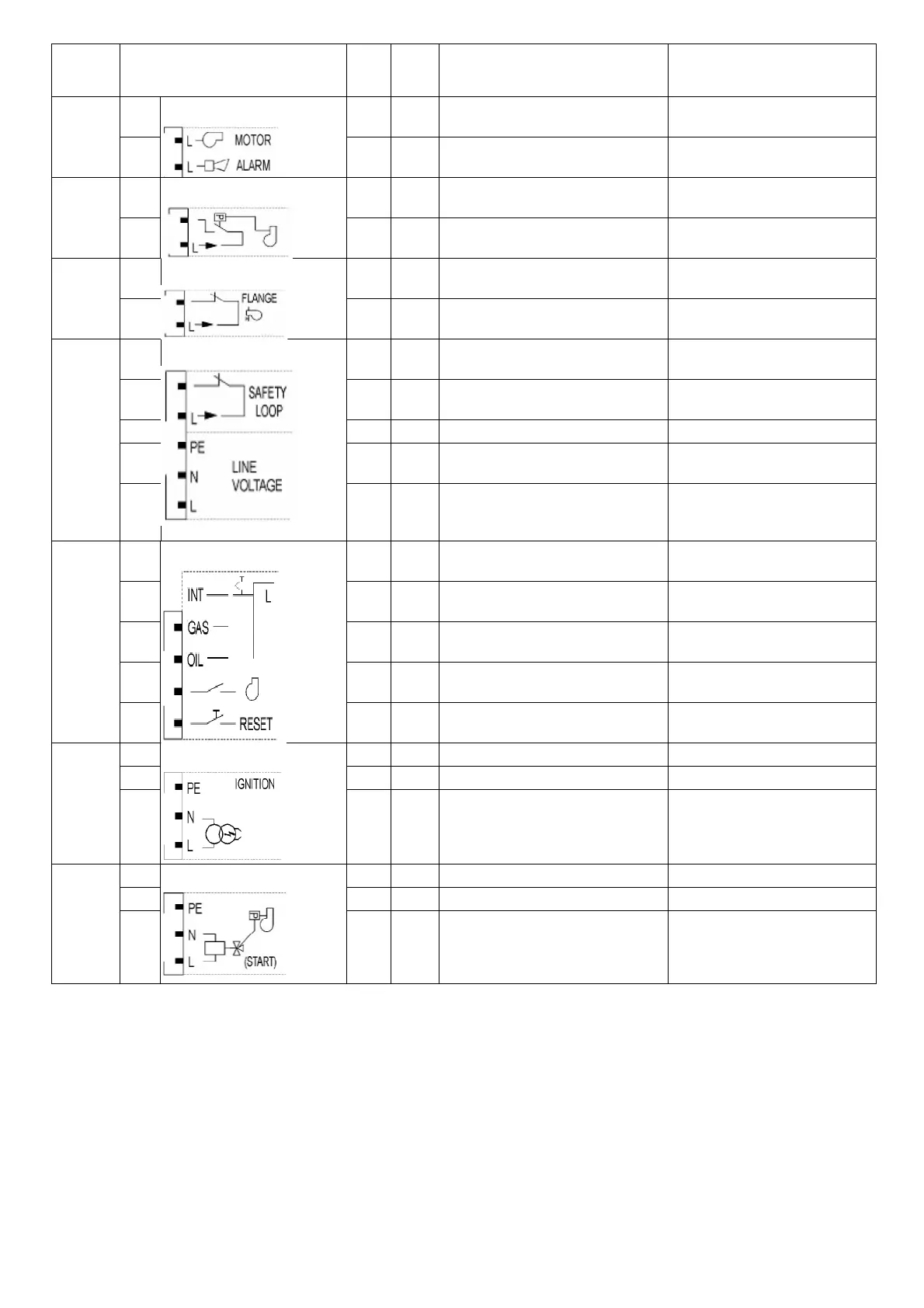
Terminal
group
Connection symbol
Inpu
t
Outpu
t
Description of connection termi- nals
Electrical rating
X3-01
PIN1 x Fan motor contactor
C 230 V +10 % / -15 %, 50...60
Hz
1 A
cos.0.4
PIN2 x
larm
C 230 V +10 % / -15 %, 50...60
Hz
1 A
cos.0.4
X3-02
PIN1 x
ir pressure switch (LP)
C 230 V +10 % / -15 %, 50...60
Hz
Imax 1.5 m
PIN2 x Power signal for air pressure switch (LP)
C 230 V +10 % / -15 %, 50...60
Hz
Imax 500 m
X3-03
PIN1 x End switch burner flange
C 230 V +10 % / -15 %, 50...60
Hz
Imax 5
PIN2 x Power signal for end switch burner flange
C 230 V +10 % / -15 %, 50...60
Hz
Imax 5
X3-04
PIN1
x Safety loop
C 230 V +10 % / -15 %, 50...60
Hz, Imax 5
PIN2 x Power signal for safety loop
C 230 V +10 % / -15 %, 50...60
Hz
Imax 5
PIN3 x Protective earth (PE)
PIN4 x Supply voltage neutral conductor (N)
PIN5
x
Supply voltage live conductor (L)
C 230 V +10 % / -15 %, 50...60
Hz, fuse 6.3 AT (DIN EN 60 127
X4-01
Fuel selection “internal” if pin 1-2 is not
used
PIN1 x Fuel selection gas
C 230 V +10 % / -15 %, 50...60
Hz
Imax 1.5 m
PIN2 x Fuel selection oil
C 230 V +10 % / -15 %, 50...60
Hz
Imax 1.5 m
PIN3 x
Fan contactor contact (FCC) or flue gas
recirculation pressure switch
C 230 V +10 % / -15 %, 50...60
Hz
Imax 1.5 m
PIN4 x Reset / manual lockout
C 230 V +10 % / -15 %, 50...60
Hz
Imax 1.5 m
X4-02
PIN1 x Protective earth (PE)
PIN2 x Neutral conductor (N)
PIN3
x
Ignition
C 230 V +10 % / -15 %, 50...60
Hz, 2 A, cos.0.2
X4-03
PIN1
x Protective earth (PE)
PIN2 x Neutral conductor (N)
PIN3
x
Start signal or pressure switch relief (air
pressure switch test valve)
C 230 V +10 % / -15 %, 50...60 Hz,
0.5 A, cos.0.4
 Loading...