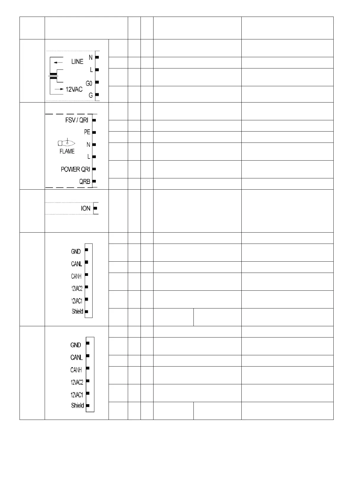
Termi- nal
group
Connection symbol
Inpu
t
Outpu
t
Description of connection termi- nals
Electrical rating
X10-01
PIN4
x
Neutral conductor (N)
C 230 V +10 % / -15 %, 50...60 Hz,
max 1 mA
PIN3 x Power signal transformer
PIN2
x
C power signal GO
C 12 V +10 % / -15 %, 50...60 Hz,
max 1.2 mA
PIN1 x
C power signal fan motor (G)
X10-02
PIN6
x
QRI... (IR detector) / QRA7... signal
voltage
Umax DC 5 V
PIN5 x Protective earth (PE)
PIN4 x Neutral conductor (N)
PIN3
x
Power signal
C 230 V +10 % / -15 %, 50...60 Hz,
Imax 500 mA
PIN2
x
QRI... (IR detector) / QRA7... power
supply
DC 14 / 21 VC Imax 100 mA
PIN1 x QRB... signal voltage Max. DC 8 V
X10-03
PIN1
x
Ionization probe (ION) (alternati- vely
QRA2…/ QRA4.U/QRA10…, refer to
section Description of inputs and out-
uts)
Umax (X3-04-PINS) Imax. 0.5 mA
X50
PIN6 x Reference ground (PELV)
PIN5
x
Communication signal (CANL)
DC U <5 V, Rw = 120 Ù, level to ISO-DIS
11898
PIN4 x Communication signal (CANH)
PIN3
x
C power supply for actuators / display
and operating unit AZL5...
C 12 V +10 % / -15 %, 50...60 Hz,
Fuse max. 4 A
PIN2
x
C power supply for actuators / display
and operating unit AZL5...
PIN1
x
Shield connec-
tion
(functional earth)
X51
PIN6 x Reference ground (PELV)
PIN5
x
Communication signal (CANL)
DC U <5 V, Rw = 120 Ù, level to ISO-DIS
11898
PIN4 x Communication signal (CANH)
PIN3
x
C power supply for actuators / display
and operating unit AZL5...
C 12 V +10 % / -15 %, 50...60 Hz,
Fuse max. 4 A
PIN2
x
C power supply for actuators / display
and operating unit AZL5...
PIN1
x
Shield connec-
tion
(functional earth)
 Loading...