Terminal
group
Connection symbol
Inpu
t
Outpu
t
Description of connection termi- nals
Electrical rating
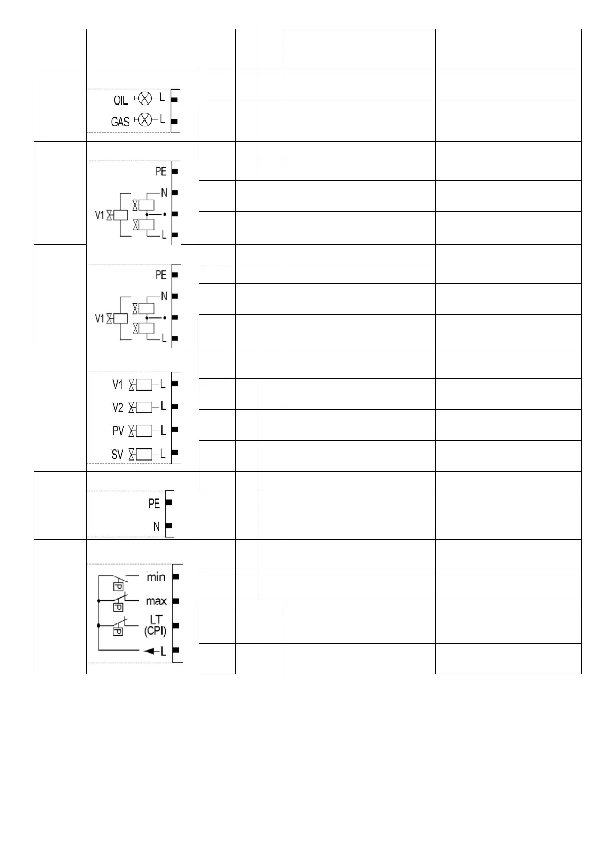
X8-01
PIN2
x
Firing on oil
C 230 V +10 % / -15 %, 50...60
Hz, 1 A, cos.0.4
PIN1
x
Firing on gas
C 230 V +10 % / -15 %, 50...60
Hz, 1 A, cos.0.4
X8-02
PIN4 x Protective earth (PE)
PIN3 x Neutral conductor (N)
PIN2
x
Wiring point for valves connected in
series
PIN1
x
Fuel valve 1 (oil)
C 230 V +10 % / -15 %, 50...60
Hz, 1 A, cos.0.4
X8-03
PIN4 x Protective earth (PE)
PIN3 x Neutral conductor (N)
PIN2
x
Wiring point for valves connected in
series
PIN1
x
Fuel valve 1 (oil)
C 230 V +10 % / -15 %, 50...60
Hz, 1 A, cos.0.4
X9-01
PIN4
x
Fuel valve 1 (gas)
C 230 V +10 % / -15 %, 50...60
Hz, 2 A, cos.0.4
PIN3
x
Fuel valve 2 (gas)
C 230 V +10 % / -15 %, 50...60
Hz, 2 A, cos.0.4
PIN2
x
Fuel valve (gas)
C 230 V +10 % / -15 %, 50...60
Hz, 2 A, cos.0.4
PIN1
x
Fuel valve (shutoff valve-(gas)
C 230 V +10 % / -15 %, 50...60
Hz, 2 A, cos.0.4
X9-02
PIN2
x
Protective earth (PE)
PIN1
x
Neutral conductor (N)
X9-03
PIN4
x
Pressure switch-min-gas, start rele- ase
gas
C 230 V +10 % / -15 %, 50...60
Hz, Imax 1.5 mA
PIN3
x
Pressure switch-max-gas (DWmax- gas)
C 230 V +10 % / -15 %, 50...60
Hz, Imax 1.5 mA
PIN2
x
Pressure switch-valve proving-gas
/ leakage test or valve closing con- tact
(CPI)
C 230 V +10 % / -15 %, 50...60
Hz, Imax 1.5 mA
PIN1
x
Power signal for pressure switch
C 230 V +10 % / -15 %, 50...60
Hz, Imax 500 mA
 Loading...