PART III: OPERATION
37
Adjustment procedure for light oil operation
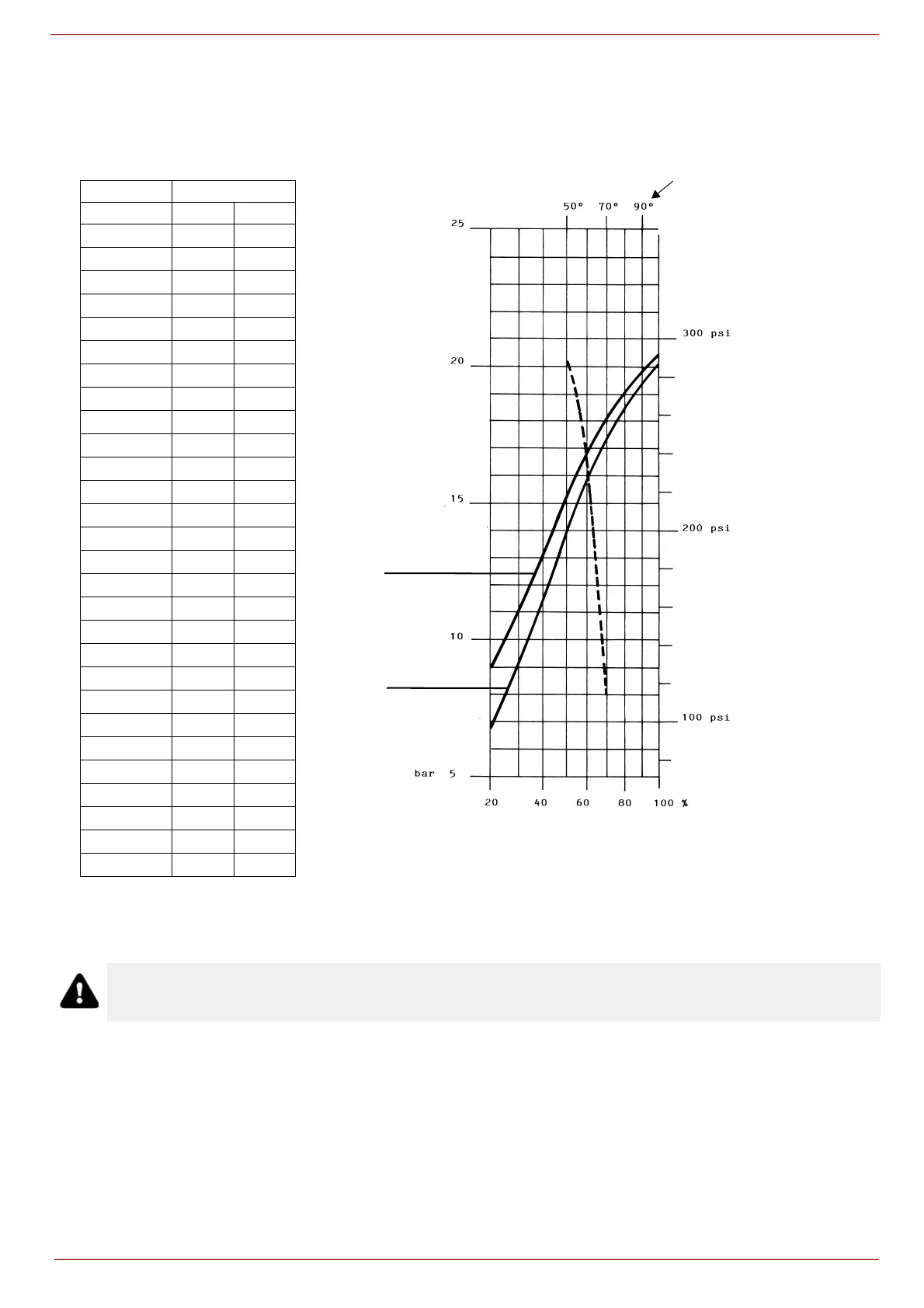
The light oil flow rate can be adjusted choosing a by-pass nozzle that suits the boiler/utilisation output and setting the delivery and
return pressure values according to the ones quoted on the table below and the diagram on Fig. 20 (as far as reading the pressure
values, see next paragraphs).
FLUIDICS W2, WR2 NOZZLE: REFERENCE DIAGRAM (INDICATIVE ONLY)
Tab. 1
NOZZLE SUPPLY PRESSURE = 25 bar
- - - - - -- - -
Atomisation angle according to the return pressure
_________ % Flow rate
ATTENTION! To achieve the maximum flow rate close completely the return line.
FLOW RATE kg/h
DIMENSIONS Min Max
40 13 40
50 16 50
60 20 60
70 23 70
80 26 80
90 30 90
100 33 100
115 38 115
130 43 130
145 48 145
160 53 160
180 59 180
200 66 200
225 74 225
250 82 250
275 91 275
300 99 300
330 109 330
360 119 360
400 132 400
450 148 450
500 165 500
550 181 550
600 198 600
650 214 650
700 231 700
750 250 750
800 267 800
Pressure on return (psi)
Over 100kg/h
Over 100kg/h
Flow rate
Atomisation angle
Pressure on return (bar)


 To Next Page