PART III: OPERATION
44
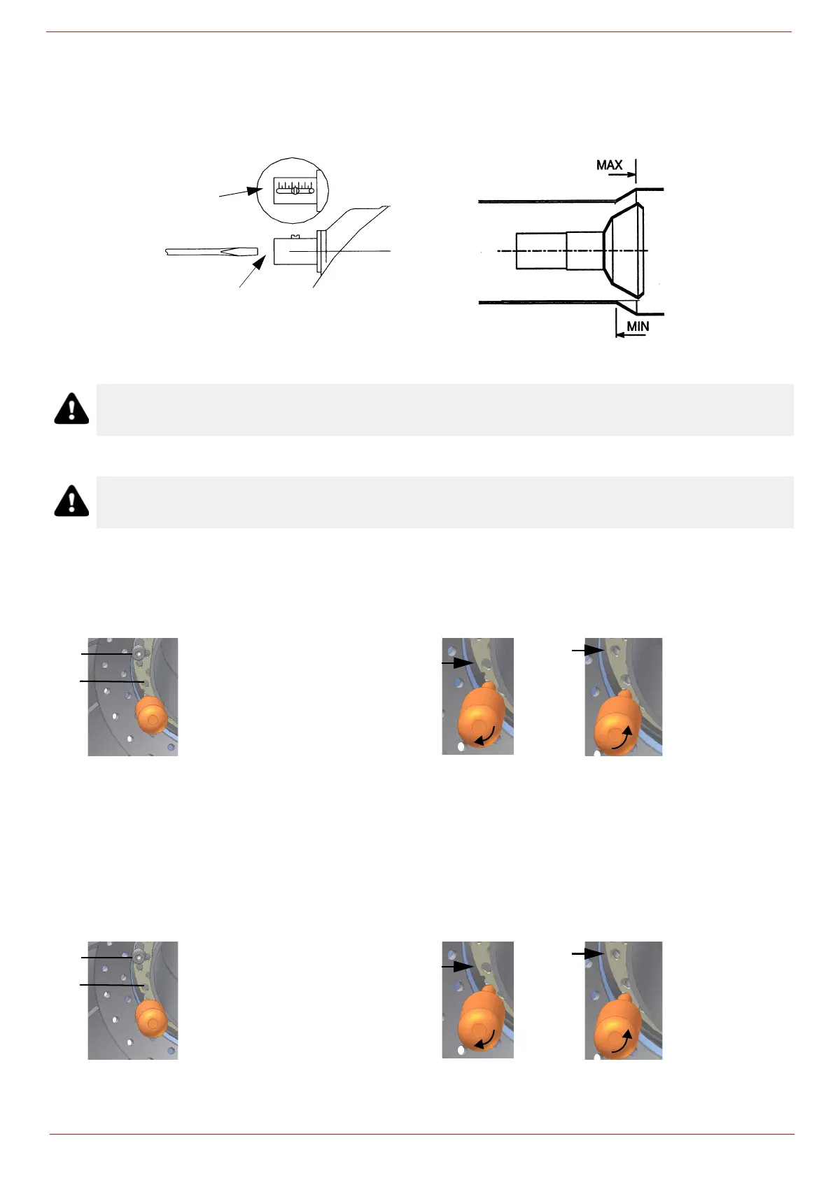
HEAD ADJUSTING
Regulating the combustion head
The burner is factory-adjusted with the combustion head in the "MAX" position, accordingly to the maximum power. To operate the bur-
ner at a lower power, progressively shift back the combustion head, towards the "MIN" position, screwing the screw VRT. The ID index
shows how much the combustion head moved.
Center head holes gas flow regulation (natural gas burners)
To adjust the gas flow, partially close the holes, as follows:
1 loosen the three V screws that fix the adjusting plate D;
2 insert a screwdriver on the adjusting plate notches and let it move CW/CCW as to open/close the holes;
once the adjustmet is performed, fasten the V screws.
The adjusting plate correct position must be regulated in the plant during the commissioning.
The factory setting depends on the type of fuel for which the burner is designed:
For natural gas burners, plate holes are fully opened
Center head holes gas flow regulation (LPG burners)
To adjust the gas flow, partially close the holes, as follows:
1 loosen the three V screws that fix the adjusting plate D;
2 insert a screwdriver on the adjusting plate notches and let it move CW/CCW as to open/close the holes;
3 once the adjustmet is performed, fasten the V screws.
The adjusting plate correct position must be regulated in the plant during the commissioning.
9xA series: 1,5 mm 5xxA series: 1,3 mm
Attention! if it is necessary to change the head position, repeat the air and fuel adjustments described above.
CAUTION: perform these adjustments once the burner is turned off and cooled.
V
D
A: opened holes
B: closed holes
B
A
V
D
A: opened holes
B: closed holes
B
A
 Loading...