PART I: SPECIFICATIONS
8
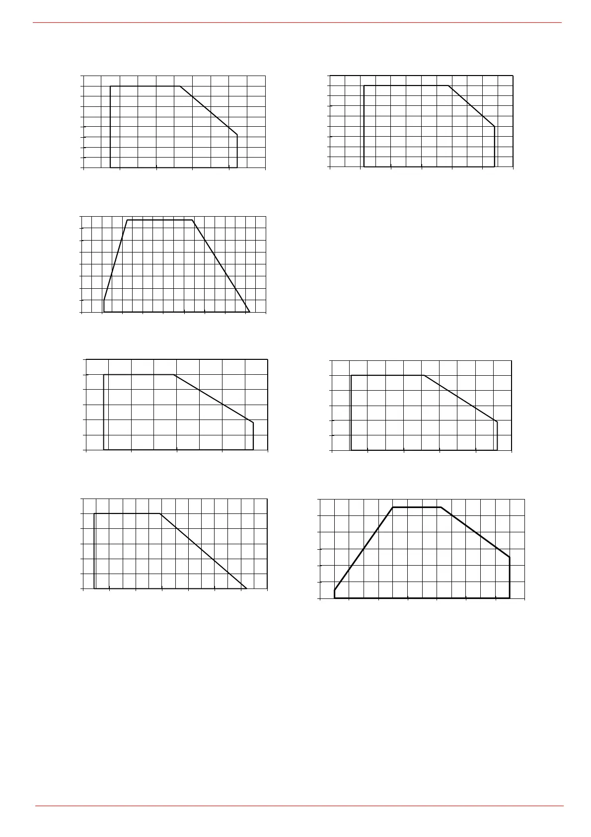
Performance curves
To get the input in kcal/h, multiply value in kW by 860.
Data are referred to standard conditions: atmospheric pressure at 1013mbar, ambient temperature at 15° C
NOTE:
The performance curve is a diagram that represents the burner performance in the type approval phase or in the laboratory tests, but does not
represent the regulation range of the machine. On this diagram the maximum output point is usually reached by adjsuting the combustion head to its
“MAX” position (see paragraph “Adjusting the combustion head”); the minimum output point is reached setting the combustion head to its “MIN” position.
During the first ignition, the combustion head is set in order to find a compromise between the burner output and the generator specifications, that is why
the minimum output may be different from the Performance curve minimum
PRESSURE IN
COMBUSTION CHAMBER mbar
RG91
kW
RG92
kW
PRESSURE IN
COMBUSTION CHAMBER mbar
RG93
kW
PRESSURE IN
COMBUSTION CHAMBER mbar
RG510
kW
RG515
kW
PRESSURE IN
COMBUSTION CHAMBER mbar
RG520
kW
RG525
kW
0
2
4
6
8
10
12
14
16
18
400 800 1200 1600 2000 2400
0
2
4
6
8
10
12
14
16
18
400 800 1200 1600 2000 2400 2800
0
2
4
6
8
10
12
14
16
0 500 1000 1500 2000 2500 3000 3500 4000 4500
0
4
8
12
16
20
24
1000 1800 2600 3400 4200
0
4
8
12
16
20
24
1200 2000 2800 3600 4400 5200
0
4
8
12
16
20
24
2000 2800 3600 4400 5200 6000 6800 7600
0
4
8
12
16
20
24
1500 2500 3500 4500 5500 6500 7500 8500


 To Next Page