EasyManuals Logo

Unipower HPL110A/S24 User Manual

Default Icon
20 pages
To Next Page IconTo Next Page
To Previous Page IconTo Previous Page
Page #11 background imageLoading...
Page #11 background image
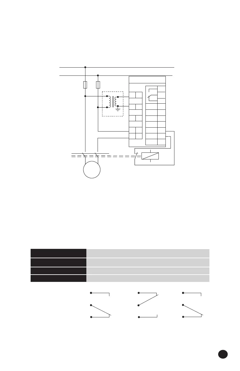
5.2 SINGLE PHASE HOOK-UP
Figure 5.2 shows correct connection for single phase mains units. The single phase
version of the HPL110A requires a 24V secondary isolation transformer (supplied) with
the L2 - Neutral side of the secondary grounded.
5.3 ALARM RELAY STATES
Figure 5.3 shows the states for the alarm relay. The relay is energized when the HPL110A is
powered and is de-energized when an alarm state exists - fail safe operation. The Relay LED
on the front panel is illuminated when the Relay is energized; this Relay LED, therefore, is on
during normal operation and is switched off when an alarm occurs.
11
Power Off On On
Alarm Condition No No Yes
Relay LED Off On Off
Limit LED Off Off Flashing
NC 9
COM 10
NO 11
Figure 5.3
M
1~
24V Secondary
Isolation
Transformer
L1
L2
K
Only if min. limit used
Motor
Fuses
11
10
NC
NC
NC
9
C
NO
HPL110A
12
13
PE
14
S1
15
S2
1 L1
3 L2
5 L3
7 k
8 l
GND
17
NC
18
16
Figure 5.2
Note: The HPL110A has a single alarm relay which is tripped by both a max. and/or
a min. limit alarm.

Questions and Answers:

Question and Answer IconNeed help?

Do you have a question about the Unipower HPL110A/S24 and is the answer not in the manual?

Unipower HPL110A/S24 Specifications

General IconGeneral
BrandUnipower
ModelHPL110A/S24
CategoryMonitor
LanguageEnglish

Related product manuals