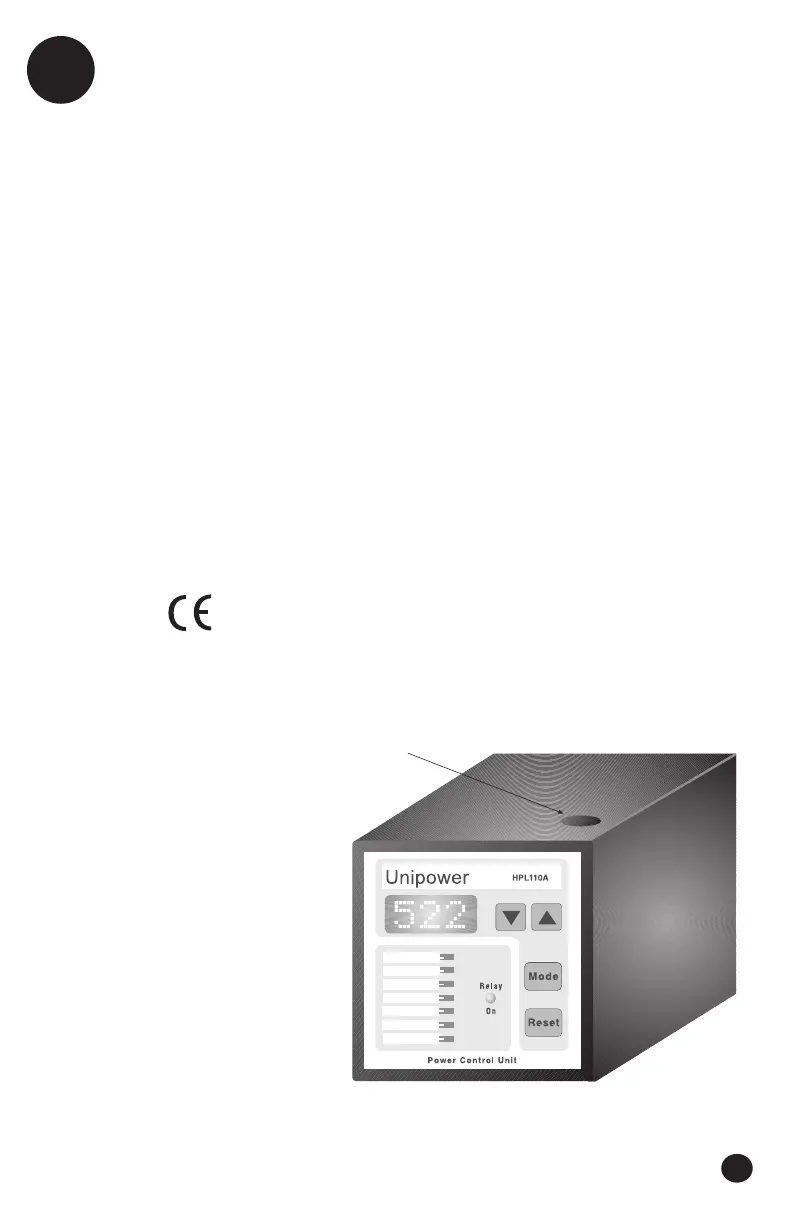
Figure 6.1
Electrical
Voltage Range: See unit for range
Standard ranges—
3 x 220, x 380, x 460, x 575
Also available—
1 x 24V for 110/220V single phase
Current Range:
Internal - max. 8A
External - N/1 or N/5 converter
Cos j Range: 0 ® 1
Frequency Range:
45 ® 65 Hz
Consumption:
Supply voltage = measurement voltage, 2 VA
Relay Output: 250VAC/5Amp
Mechanical
Housing: Noryl
Mounting: Panel mounting for
2.64” x 2.64” cut-out (67 x 67 mm)
Min. mounting depth 5” (125 mm)
Protection Class: IP54
Terminals: 12 AWG max., 20A
7 in.lb tightening torque (0.8N.m)
Operating Temperature Range:
+5 ® +122°F (-15 ® +50°C)
Weight: ~1lb (0.5 kg)
Dimensions:
D 4.4” x B 2.85” x H 2.85”
(D 112 x B 72 x H 72 mm)
Functions:
DIP Sw. 1 “OFF” = Programming Enabled
DIP Sw. 1 “ON” = Programming Disabled
(Protected)
DIP Sw. 2 “OFF” = Alarms Normal
DIP Sw. 2 “ON” = Special Power-Down
Alarm Block Function
Enabled, see 8.8,
page 18
CE mark to EN50081-1, 50082-2, 61010-1
UL certified to UL508 (USA) and C22.2 No.14-M91
(Canada) standards for Industrial Control Equipment
 Loading...